Custom metal fabrication has many challenges, but one of the most challenging can be fabricating a precision tube frame. When building a tube frame with complex geometry, bends in multiple planes, and tight geometric tolerances, the smallest detail being wrong in the process can make a joint that does not fit, or geometry that will not work. At American Precision Engineering we utilize technology, engineering, and operator skill to assure we make precision parts with maximize efficiency.
Quality and efficiency start at the design phase.
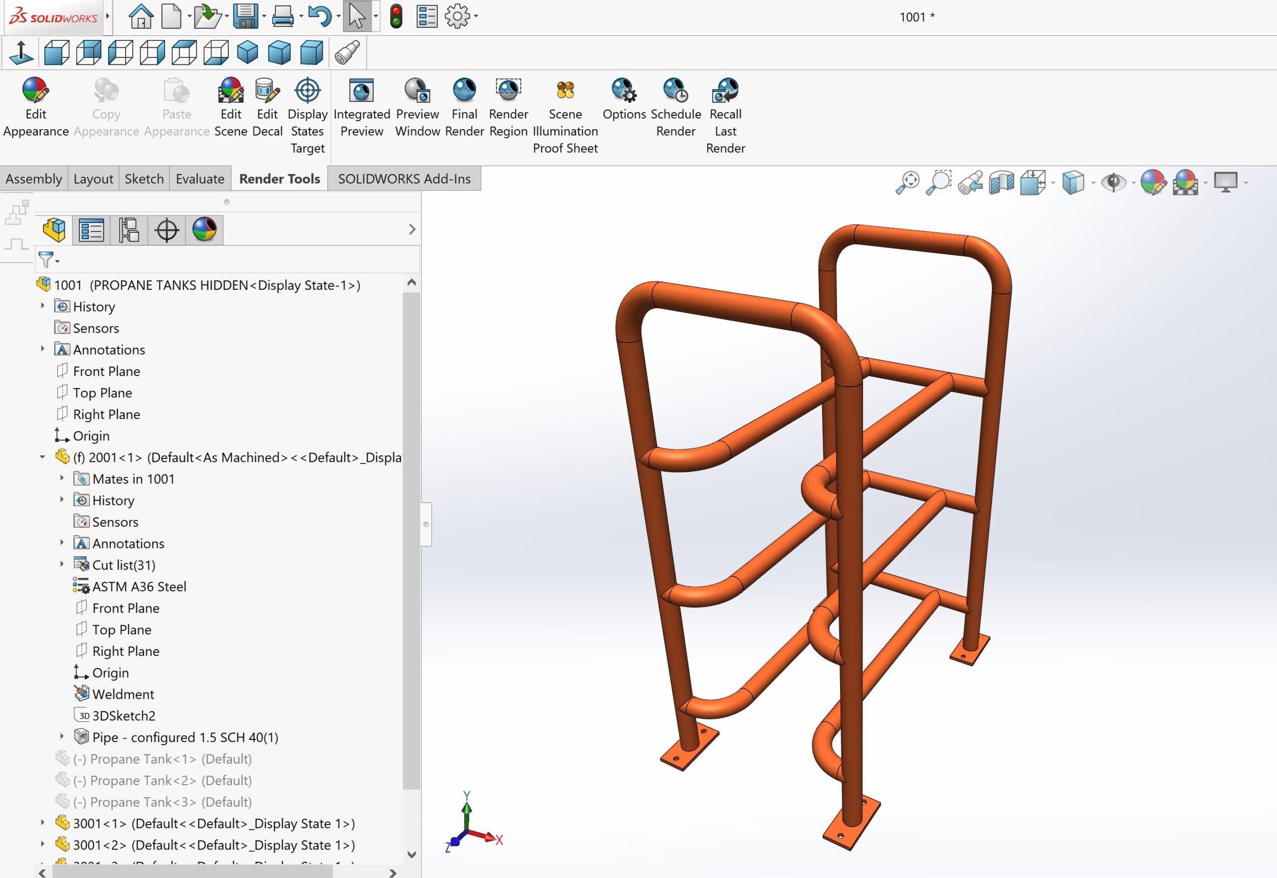
Attention to detail in the design phase sets a project up for success. It’s hard to make high-quality parts from a low-quality design and that is why APE puts such a high emphasis on creating an optimum CAD model in SolidWorks.
With today’s advanced CAD software tube frame weldments can be designed with ease. In the hands of the right engineer, this software can also be a powerful weapon to improve quality, cost, and scedule. At APE, we start each precision weldment project with a highly detailed CAD model in SolidWorks. In addition to being our primary design tool, by utilizing this technology we are also able to do a several key things that improve our quality and efficiency in tube fabrication. First, the software allows us to convert our model to files to be used for laser cutting the tubes on a CNC Tube Laser. Second, we are able design precise welding fixturing systems to securely hold the components in exactly the right place for welding. Without SolidWorks, and a skilled engineering team, neither of these would be possible.
Laser Cut Tube For Speed & Precision
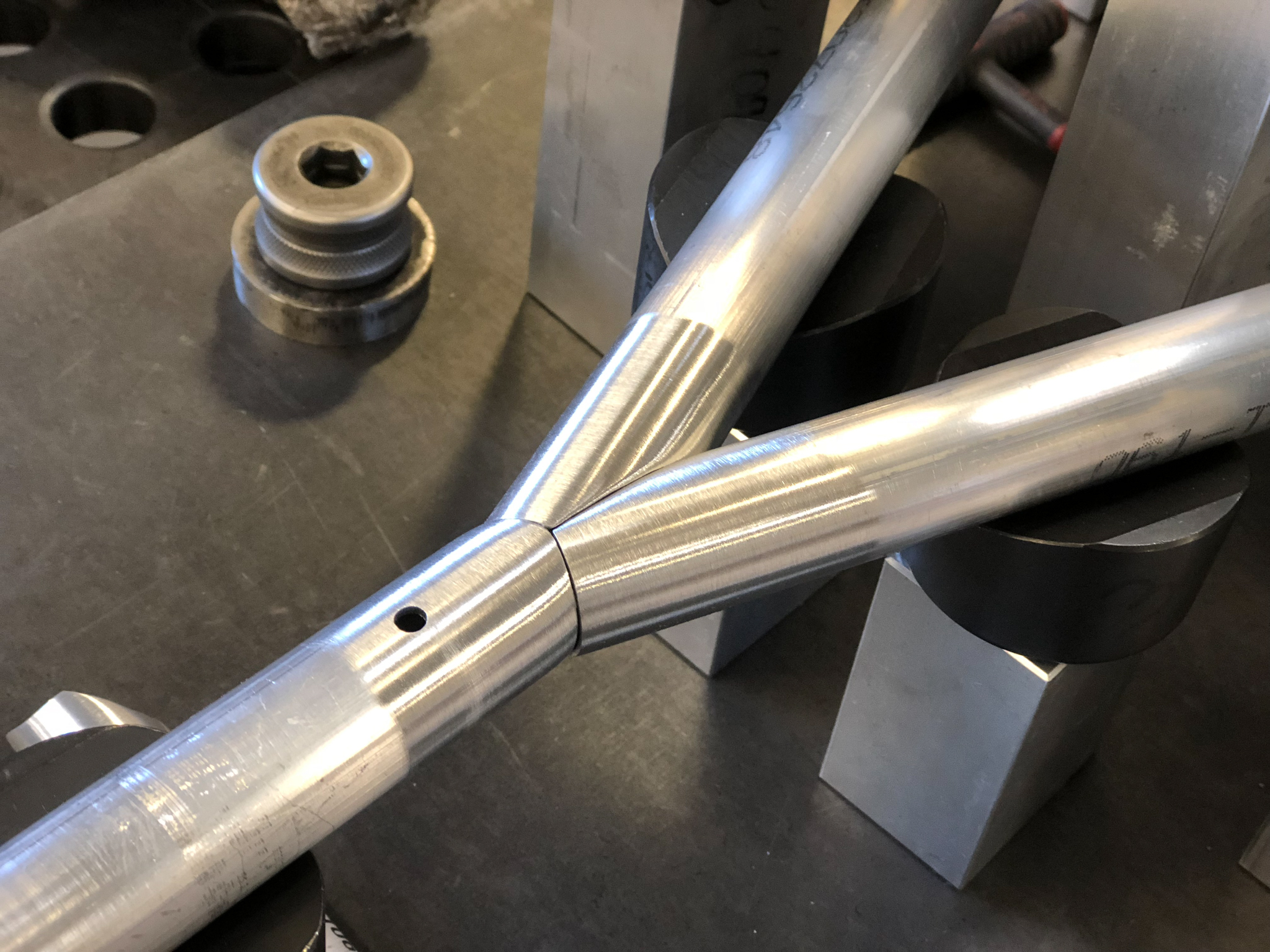
With CNC laser cut tube, complex joints can easily be fabricated.
With todays modern tube laser machines an entire new spectrum of fabrication has been opened up in the past decade allowing us to repeatedly fabricate incredibly complex frames with perfect joint fit in a fraction of the time compared to using alternative methods. Having properly fitting connections not only speeds up the time fitting the components together, but ultimately results in stronger welded connections because welders don’t have to span large gaps in the fit-up. Additionally, with proper engineering & planning, using a tube laser allows us add holes as well as etch layout lines for bending, assembly, and part tracking saving valuable time during fabrication and reducing overall project cost and lead time.
Engineering a Better Process
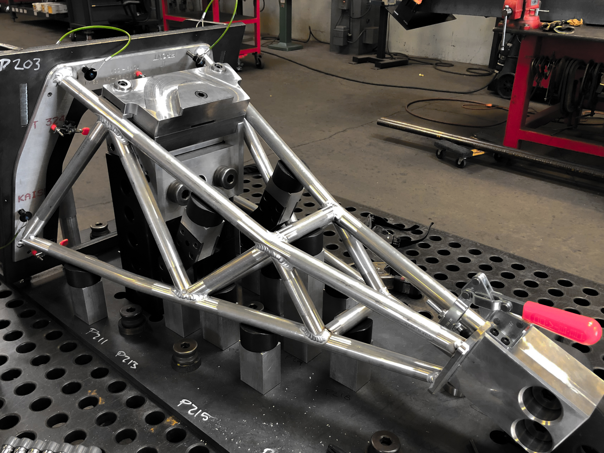
A well designed fabrication fixture allows the tube components to quickly, and securely be held for welding. It should also gives the welder free access to the joints for welding.
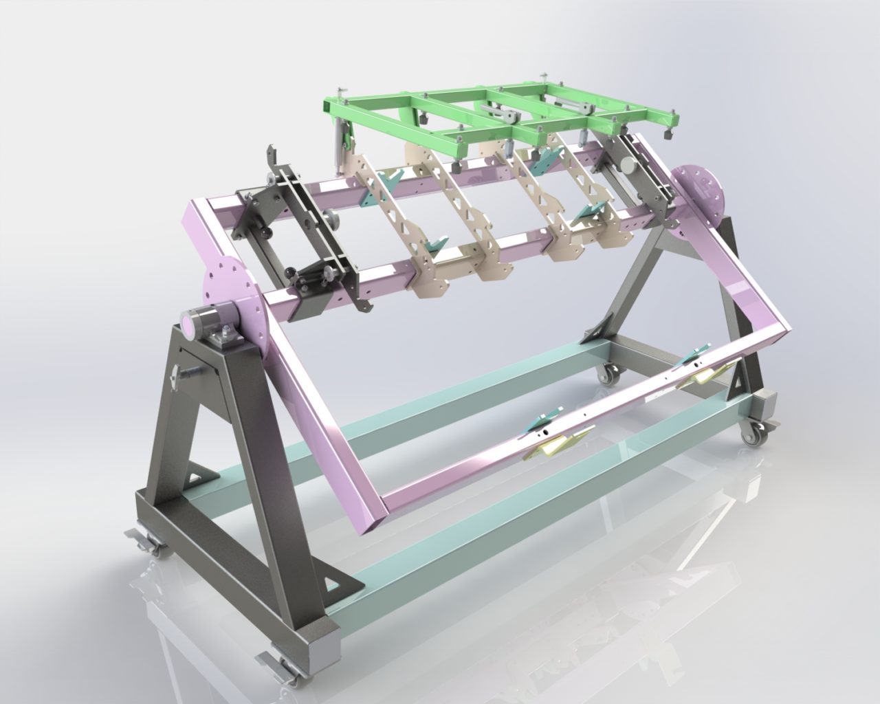
Because we design each component in SolidWorks and build a welding fixture to hold the components exactly where they are designed to be, we are able to efficiently fit and hold all the components for welding. Sometimes the fixture can be an advanced fixture used for production as shown above, but other times we utilize our modular fixturing tables to quickly assemble a fixture for a one-off component. While simple tube frames can be built without a fixture in order to get consistently high quality welded frames well thought out fixture is a must. Utilizing our modular fixture table, APE fabricators are able to quickly and easily build a fixture for many projects in a matter of minutes, a task that can take days with alternative means.
High Quality Machines Make High Quality Parts
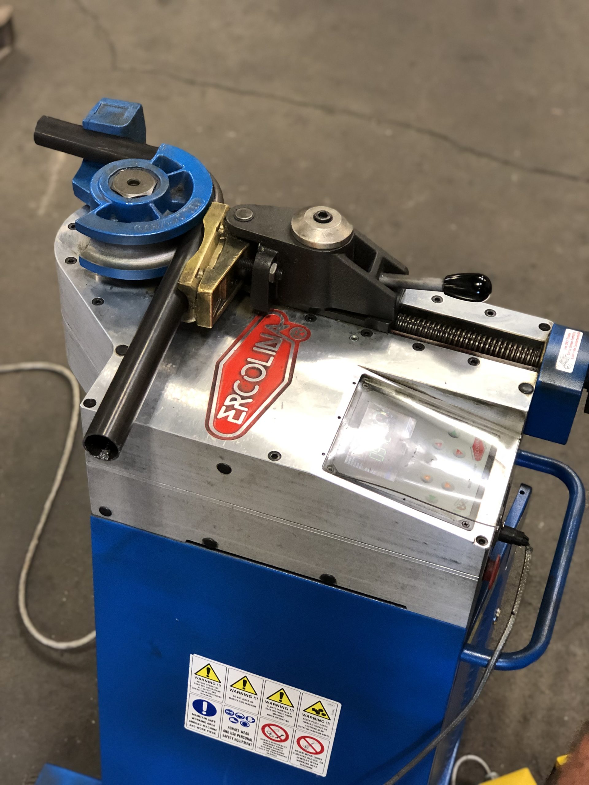
A high quality tube bender, like this one from Ercolina, can make precision bends in tubes with ease.
In order to make quality bent tube, you have to have quality equipment. That is why we have invested in an Ercolina NC controlled tube bender to accurately, and repeatably make high precision bends in tubes up to 2” in diameter. The Ercolina bender allows us to program in spring back, bend angles, and bend sequence and save the programs for quick retrieval for repeat projects.
Skilled Fabricators Are a Must!
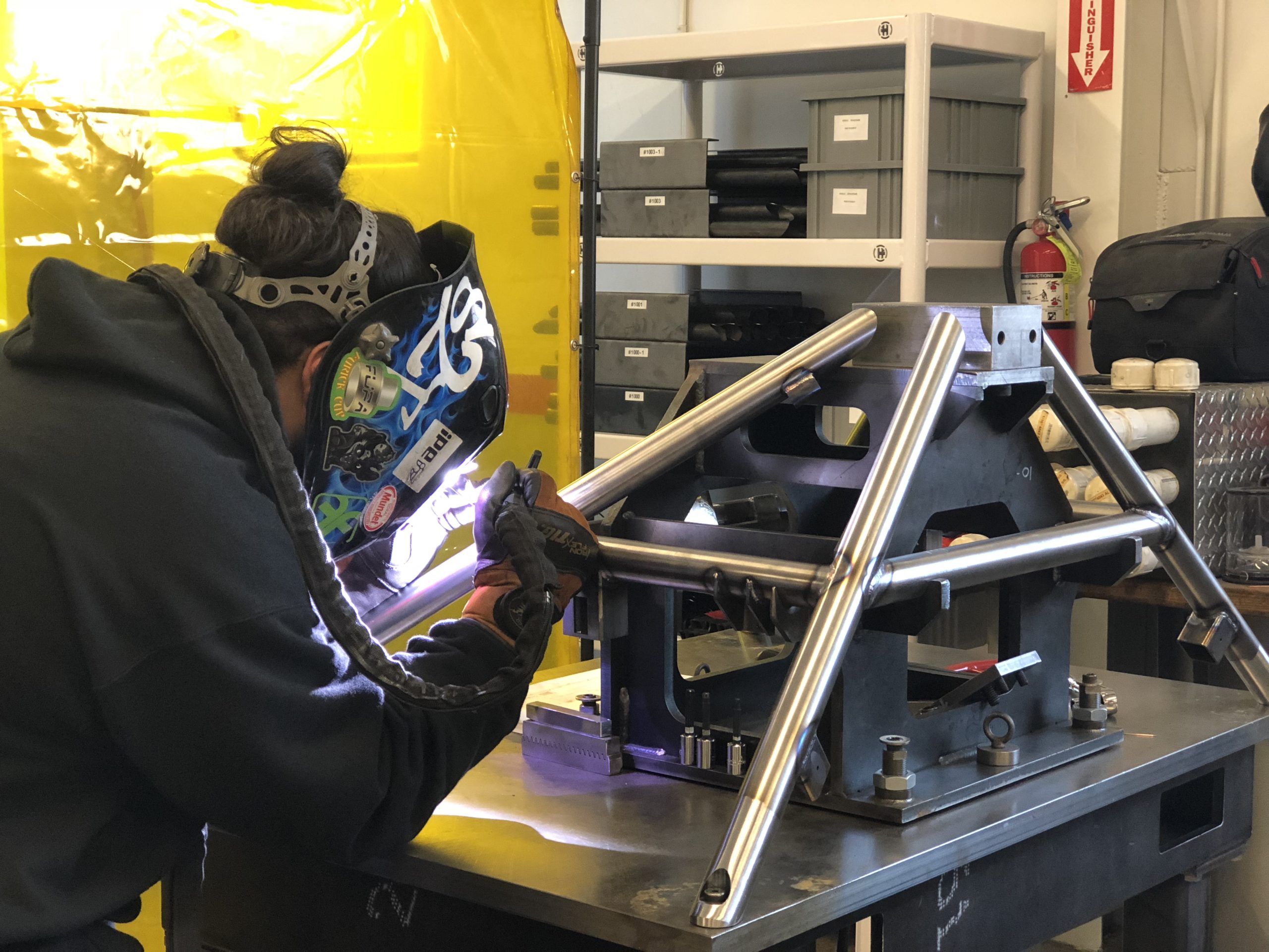
Skilled fabricators are needed to consistently produce high quality weldments
No matter how advanced your technology is, at the end of the day you still need to have skilled fabricators to make a precision tube frame to the quality standards required of aerospace, automotive, and other advanced manufacturers. That is why we invest heavily in our skilled craft employees that work hard to continually improve their skillset and knowledge. It is hard to replace experience in tube fabrication, and we are proud to have a team of skilled and dedicated fabricators ready for the next challenge.
When it comes time for you to start your next tube frame project let us know how we can help.
KEYS TO A SUCCESFUL TUBE FRAME PROJECT
Blog
The Challenge:
A manufacturing company was building 50 mobile COVID testing centers in a matter of only a couple months which required a large volume of precision weldment fabrication. The project required building 50 tubular steel chassis and associated components so that they could be assembled with the other elements at the manufacturer’s headquarters. It was a fast-paced job with lots of components and several logistics hurdles to overcome to deliver on-time.
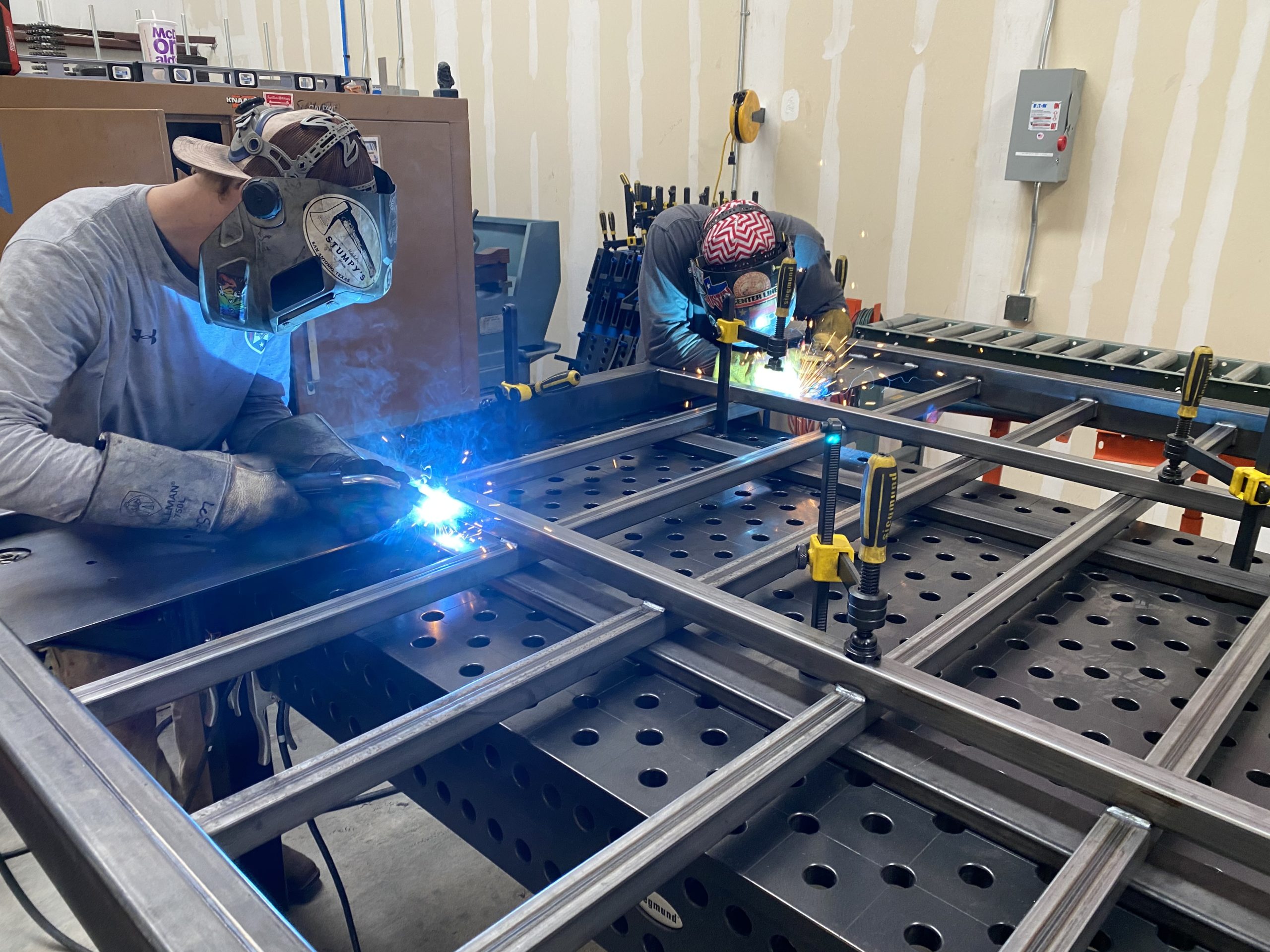
Utilizing a precision fixturing table allowed us to quickly produce highly accurate tube frame weldments
Design:
While the design of the system was nearly complete when the customer reached out, we knew that to be able to meet our customers schedule we would have to optimize the design for efficiency and quality. Utilizing our proprietary Design-Thru-Fab work flow, we modified components to include tab & slot features and laser layout lines to eliminate fit-up time and potential mistakes. Additionally we changed connection details to reduce the amount of welding required for each frame. These design enhancements would allow us to work quickly while keeping quality at its peak.
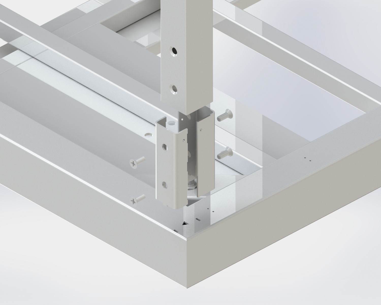
By engineering the fabrication and assembly of each component during the design phase APE is able to consistently produce higher quality parts faster.
Fabrication:
The fabrication process included laser cutting tubes, laser cutting plates, CNC press brake forming, and some light machining operations. Utilizing these cutting-edge fabrication techniques for each component during the fabrication process allowed APE to produce high quality weldments in very short cycle times.
Because we have a high precision modular fixturing table, we were able to fit the components of each frame together in a fraction of the time required by typical fabrication techniques. These fixturing tables also allowed us to easily keep a level of precision that was well within the tolerance of the project.
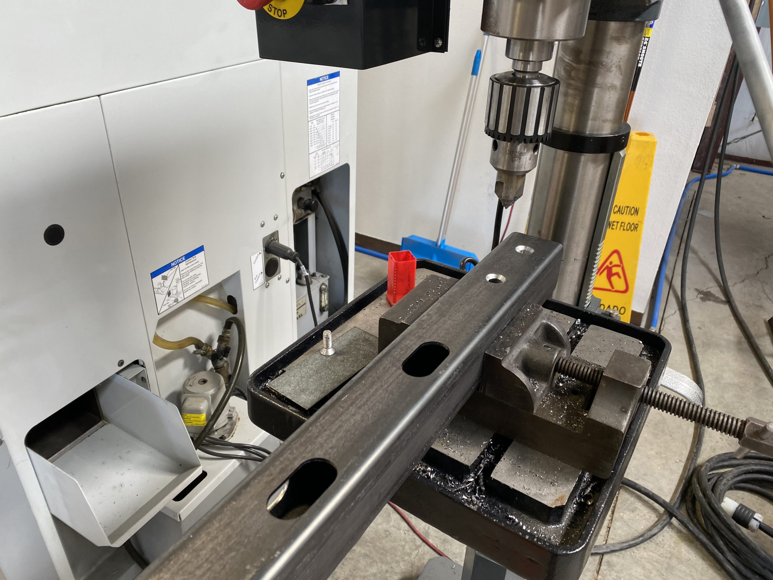
Using a drill press to countersink holes in laser cut steel tubes
The Results:
Because of APE’s innovative Design-Thru-Fab approach to custom fabrication projects, 50 frames were delivered on time to specification to the customer so they could get the testing stations deployed during a critical moment in the COVID-19 pandemic.
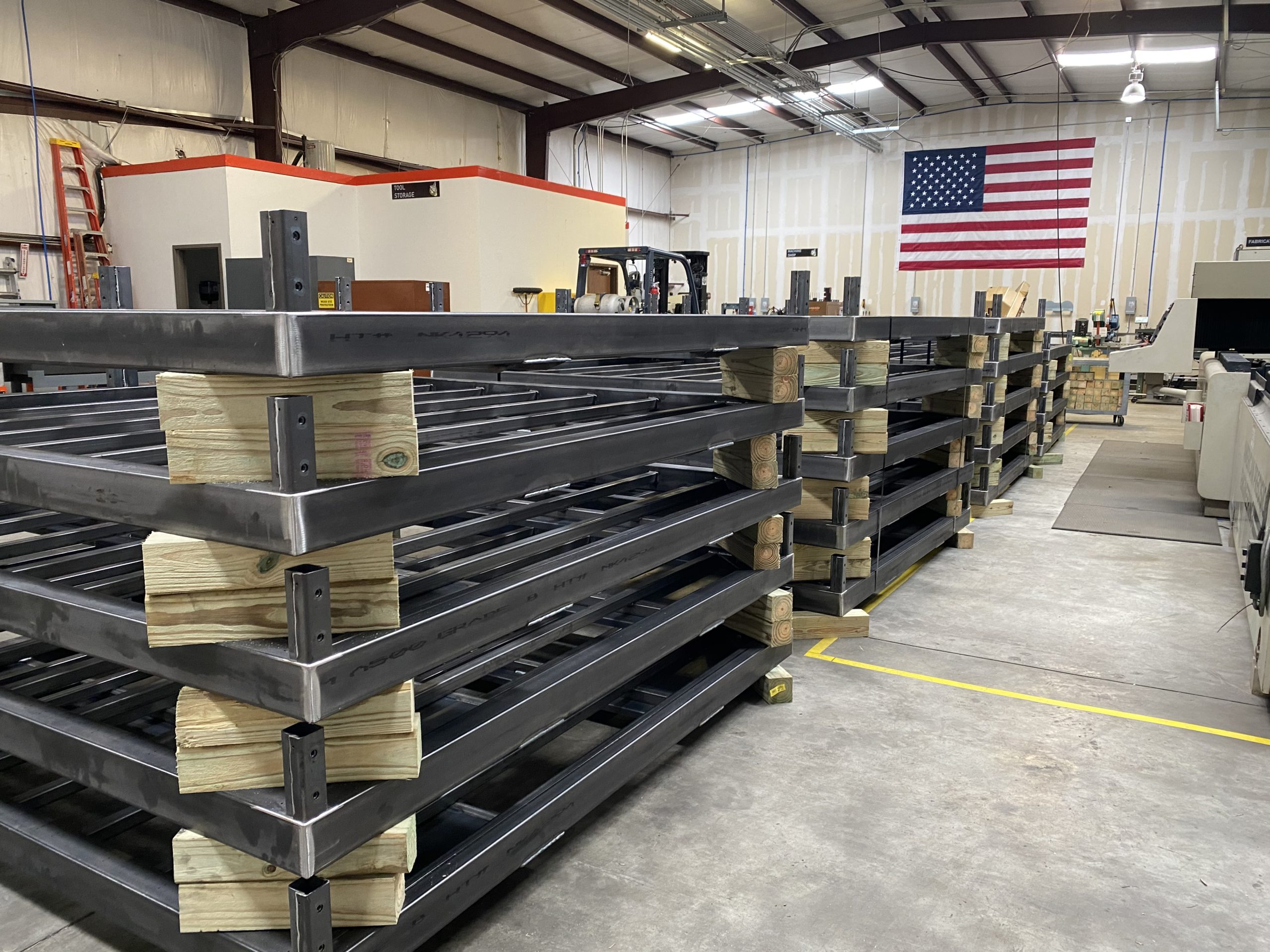
When a well engineered plan is executed with precision, large volumes of products can be produced to high quality standards quickly.
One of the keys to precision fabrication is having a well-designed welding fixture that positions and holds the parts where they need to be while the welding operation takes place. While this seems simple, in practice, it can be much harder to do. In this blog, I go over 6 things that will help you design a better fixture to make better parts.
A well designed welding fixture should allow parts to be installed quickly and put the welder in a comfortable position to make quality welds. This example is a precision welding fixture for an industrial rail product.
1) What are you trying to hold with your fixture? One key consideration that is easy to overlook is holding parts that don’t need to be very precise in an overly tight fixture. While it could be reasonably argued that there is nothing wrong with making parts to a tighter tolerance then the customer asked, you might be making it harder to obtain the tolerance on the features that actually matter. For instance, holding the profile of a bent tube might not need to be held nearly as tight as the face of the machined block it attaches to. By trying to hold the tube profile perfect you could be inducing stress that once the part is pulled out of the fixture, it springs the piece its attached to out of tolerance, ruining your part. You should be reviewing the tolerance on the project and working on holding the high tolerance features first, before assuming everything needs to be perfect. Often, through this process you will find out that certain parts do not need the tolerance that you imposed on them and it will result in a more successful project through reduced labor costs, and less headache.
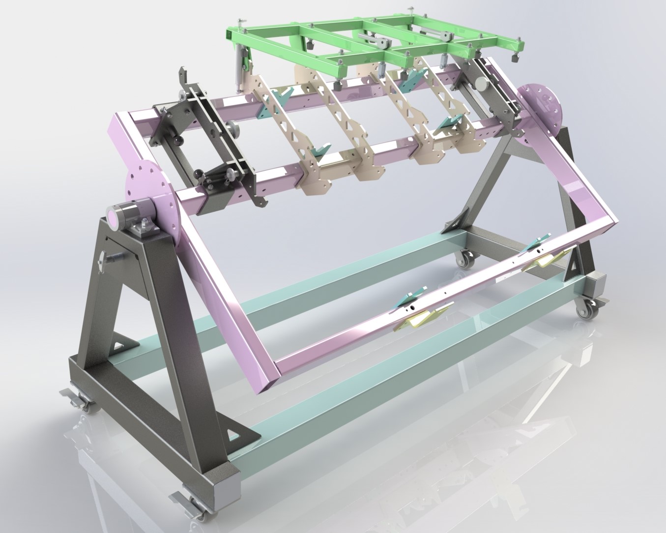
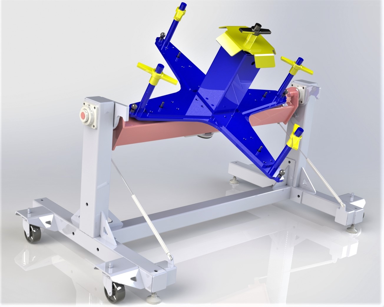
A welding fixture for a large industrial part. This fixture allows the part to spin on two different axis’ so the welder can reduce wasted motion and always weld in the flat position.
2) How easy is it to get the parts out of your welding fixture? There are those that have, and those that will eventually make a fixture that once the parts are welded they don’t come out without destroying something. While this is an extreme example of a bad weld fixture, some fixtures require so much disassembly and reassembly that you might as well be cutting something apart. While bolts can be useful to make disassembly easy for certain applications, it is much better to use quality clamps like Destaco or other lever action clamps when possible. Bolts take longer to install and remove and have a tendency to have threads get worn and damaged over time. It is a good practice to try and use pins & clamps in place of bolts in most cases to hold a tighter position, and get the parts out quickly. If bolts must be used, then you should use countersunk bolts or shoulder bolts to make sure concentricity of the holes.
A well designed fixture should allow parts to be installed and removed quickly and easily
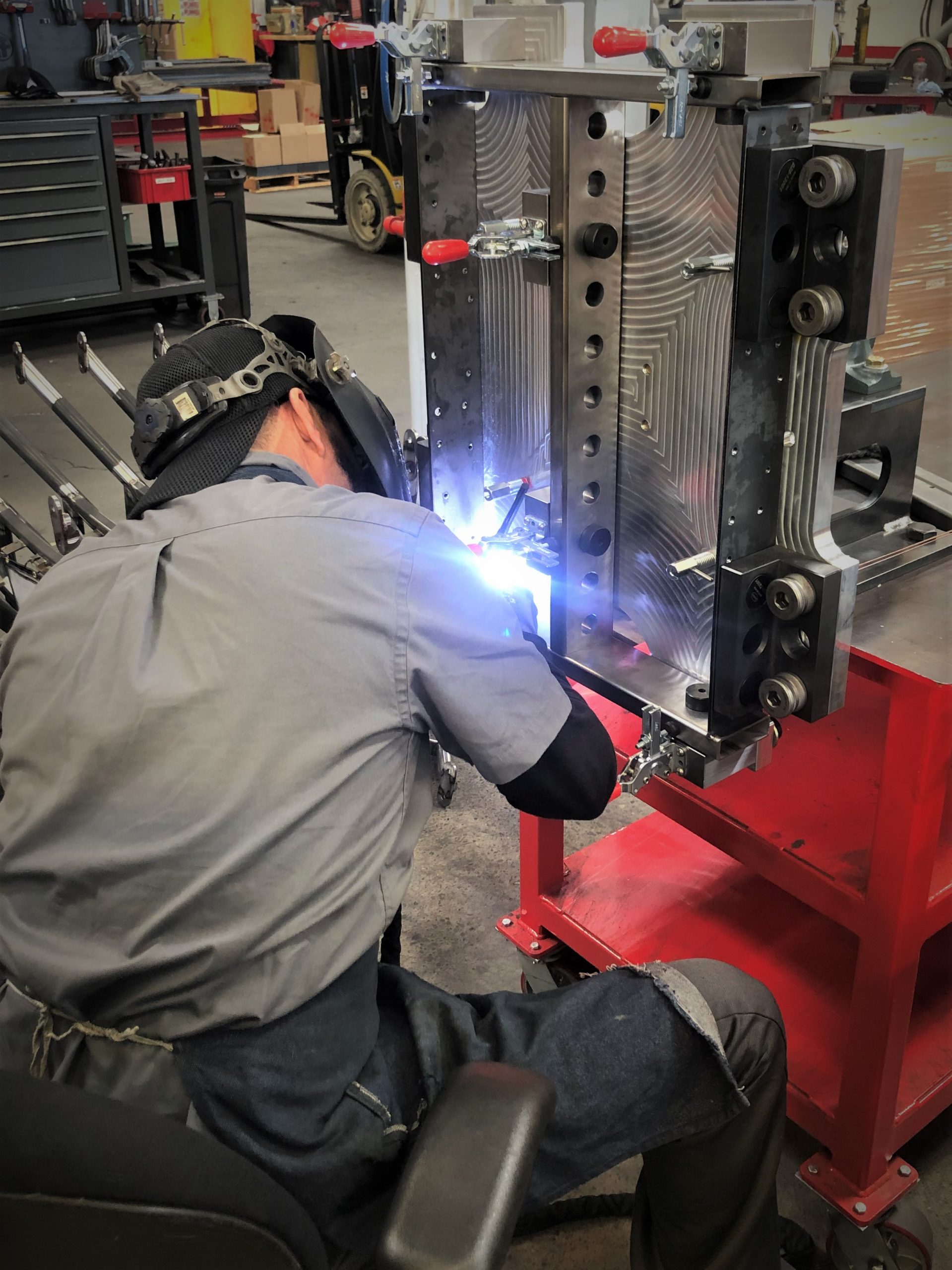
3) How easy is it to weld in the fixture? After you have an idea of how to hold the parts where they will be, and you’ve checked that you can get the parts out, the next thing to review is how easy it will be to weld the parts. This means that you need to check that there is plenty of clearance around the joints to fit a welding torch AND you have a line of sight to see what you are welding. As you do this you might find out that you need to go back and revisit some of your ideas of how you were originally going to hold the parts. Depending on the welding process (MIG, TIG, Robotic, etc) the amount of clearance and line of sight you need will be different, but it’s hard to make quality welds when you can’t see what you are doing so this should be a high priority. Another consideration of how easy it is to weld is the position of the weld operator. You should do whatever is possible within reason to make the welder as comfortable as possible. This means that you might be making a rotating fixture, or placing it on an adjustable height table so that the welder can be in the optimum position as much as possible. They will thank you for designing an easy job for them, and you will thank them for producing quality welds.
This fixture allows the welder to sit in a chair and spin the part to always weld in the same position. Notice the use of toggle clamps to quickly remove parts after welding.
4) Can you make adjustments to the fixture? Quality has two aspects: consistency and tolerance. If you chase tolerance you will have a hard time catching it consistently and that’s not good for business. However, if you focus on consistency, getting and staying within tolerance is much easier to not just obtain, but also to maintain. I strongly recommend graphing your QC results so that you can get a visual representation of your consistency as shown on the example below. Hopefully your parts start out within tolerance, but you should plan for ways to adjust in case it doesn’t. As anyone that has ever welded knows, the parts don’t like to stay where the started due to weld shrinkage. And to a large extent the fixture will help minimize the amount of deformation that you will see during welding. It is for this reason that you should design your fixture to hold the parts exactly where you want them to end up, BUT you should build in a way to adjust, and strive for consistency first. As you can see from the graph below, it took until the 10th unit to get a consistent dimension of these critical features because of small variations in the welding procedure from part to part. When focusing on being consistent, and graphing your results you will see when it is time to make an adjustment to your fixture. If you’ve done it right, it should be any easy fix, not a total replacement. On the project highlighted below, after part 15, we added a shim to our fixture assembly and you can see the 0.5mm change to bring our finished part to the middle of the tolerance. By focusing first on consistency and having a fixture that we could easily adjust allowed us to reduce the chances of having a failed part.
You should focus on consistency before you focus on tolerance. It took this project 10 parts to get consistent. After consistent geometry was obtained a small change in the fixture was made at number 16 to move the geometry closer to the center of the tolerance.
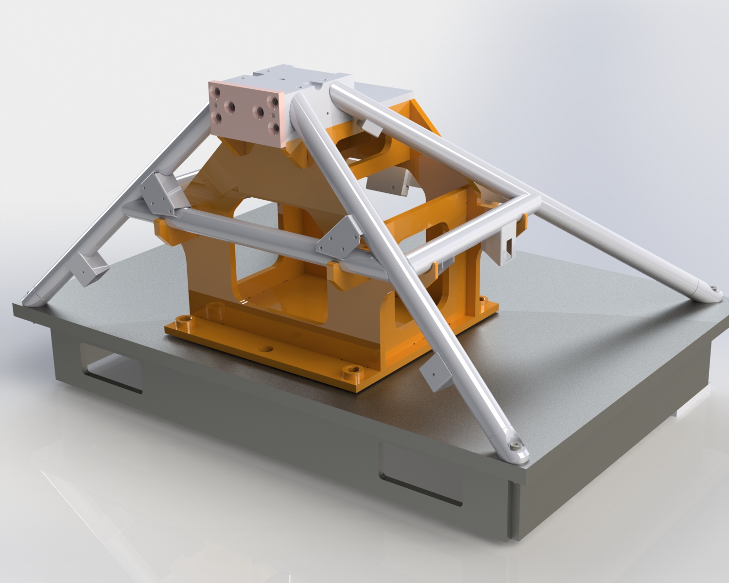
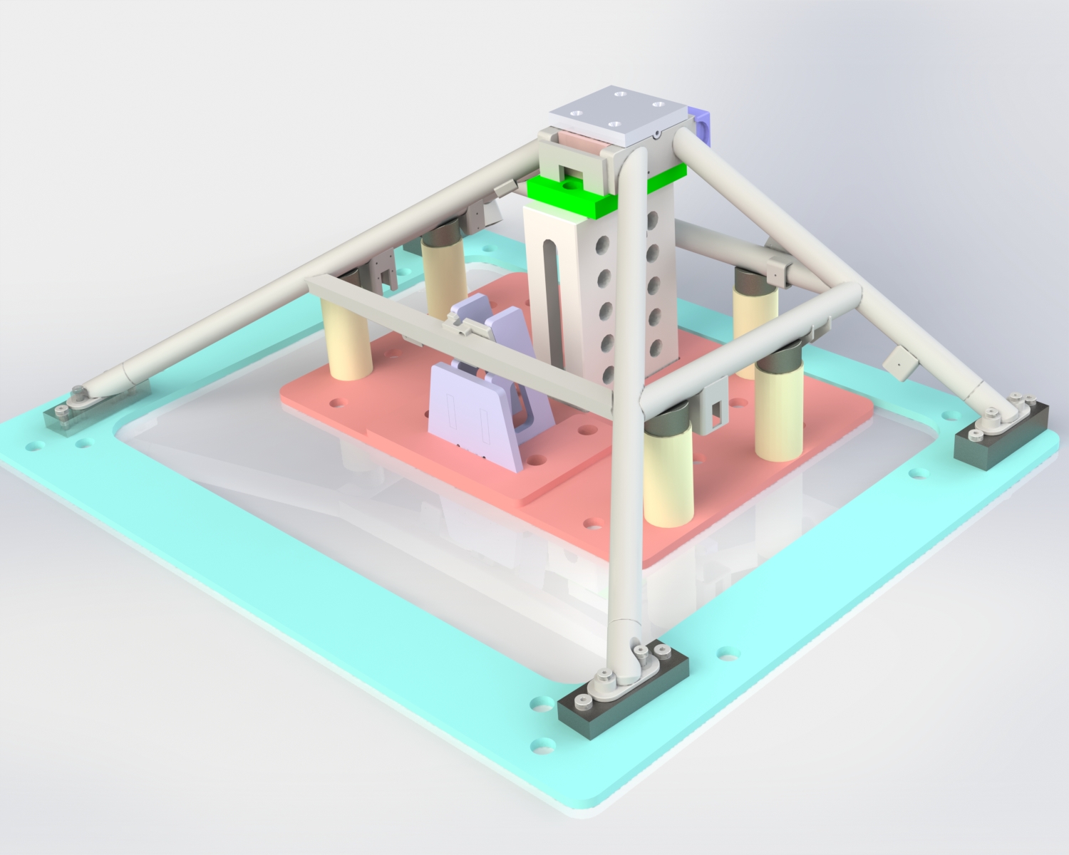
5) Does your fixture need a fixture? When deciding whether you fixture will be made from laser cut and welded parts or machined components it can be enticing to go with the (usually) cheaper option of welding some plate together. When considering this decision the general rule I like to use is a factor of 10 for my fixture part tolerance relative to my production part. For example: A laser cut feature will have a positional tolerance of +/- .005” depending on the laser. 10 x .005” = .050” (+/- .025”) This means that if the part you are fixturing has a tolerance of .050” or greater I would be ok using a laser cut feature to locate it. Parts that have tighter tolerance features will require machined or precision ground fixture parts. If you are using a laser cut and welded fixture than you should be very careful of how you plan on putting it together and how you verify the final geometry. While the use of laser cut tabs and slots can make building your welded fixture quicker, it is very easy to forgot about your tolerance stack-up and end with a fixture that will not give you the results you want. When welding a fixture I strongly recommend using components from Bluco or Siegmund to help facilitate accuracy, and minimize the amount of welding required to reduce weld distortion. My personal favorite is to incorporate machined parts, welded parts, and modular fixturing components into a fixture at the same time to optimize the quality, while minimizing the time and money spent building your fixturing system.
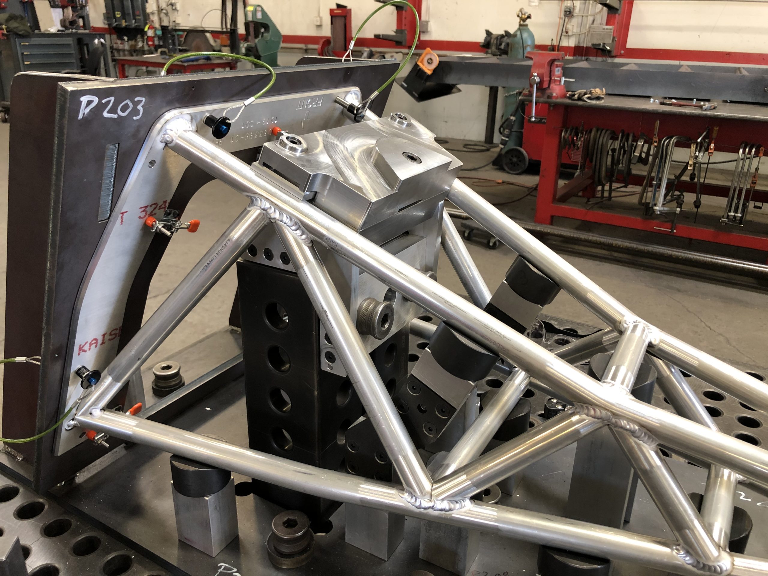
This fixture is made up of a combination of welded, machined, and modular components.
6) Can you use your fixture for QC? As almost all precision welded components will require some level of dimensional verification why not use the fixture? If you are able to use the fixture as a go-no-go, or as a precision platform from which to take measurements from, then you will be saving time and money. Even if the part will be CMMed or laser scanned after it is done, designing points in the fixture to use as dimensional verification will speed the process and also give the welders an immediate feedback loop on their performance. Having the fixture also serve as an inspection tool not only helps the welders improve more quickly, but it eliminates the waste associated with moving parts to an inspection or secondary operation that are out of tolerance.
A precision tubular frame can made productively and with consistently high quality with a well designed welding fixture.
While every tooling and fixturing project will have its own unique problems, these tips should get you headed down the right path towards productively making high precision parts. If you have a project that you need some help designing a fixture for don’t hesitate to give us a call.
HOW TO DESIGN A PRECISION WELDING FIXTURE TO MAKE BETTER PARTS FASTER

The Challenge:
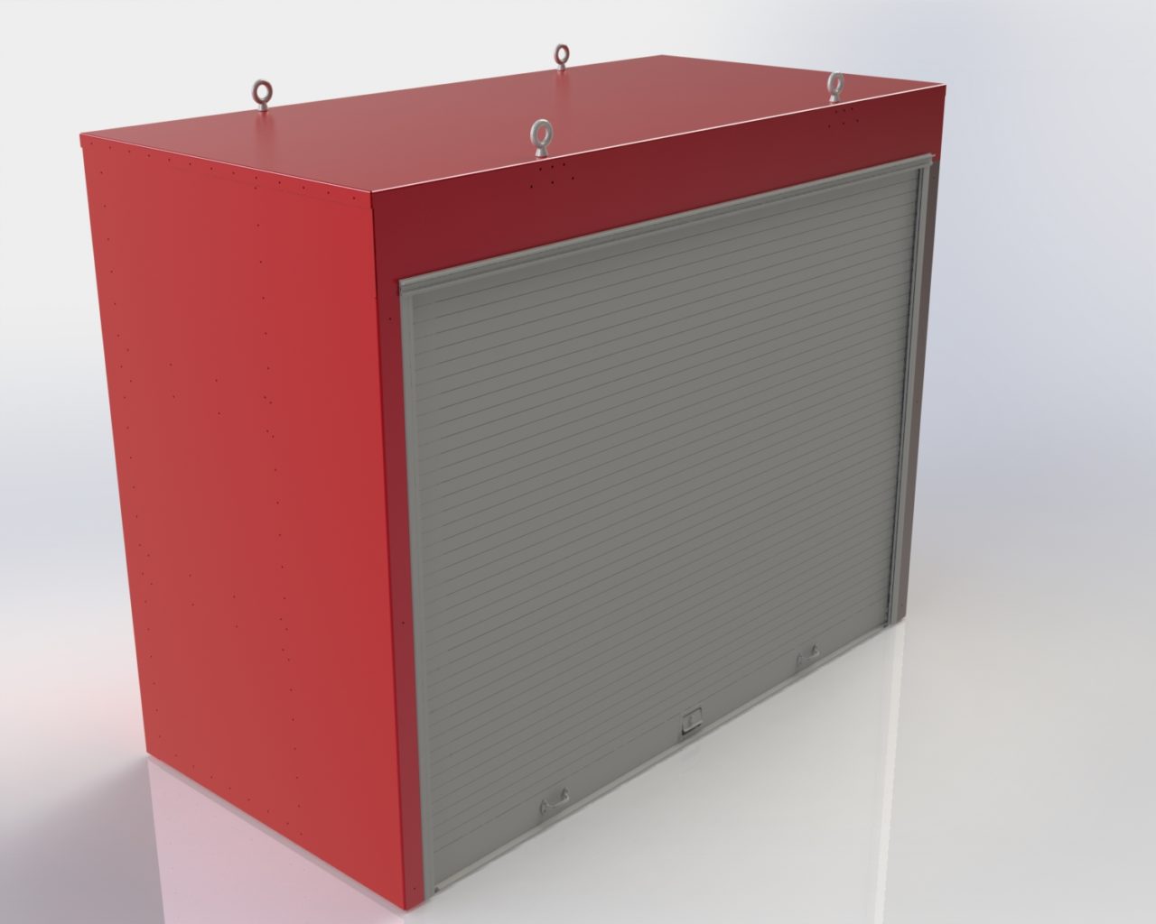
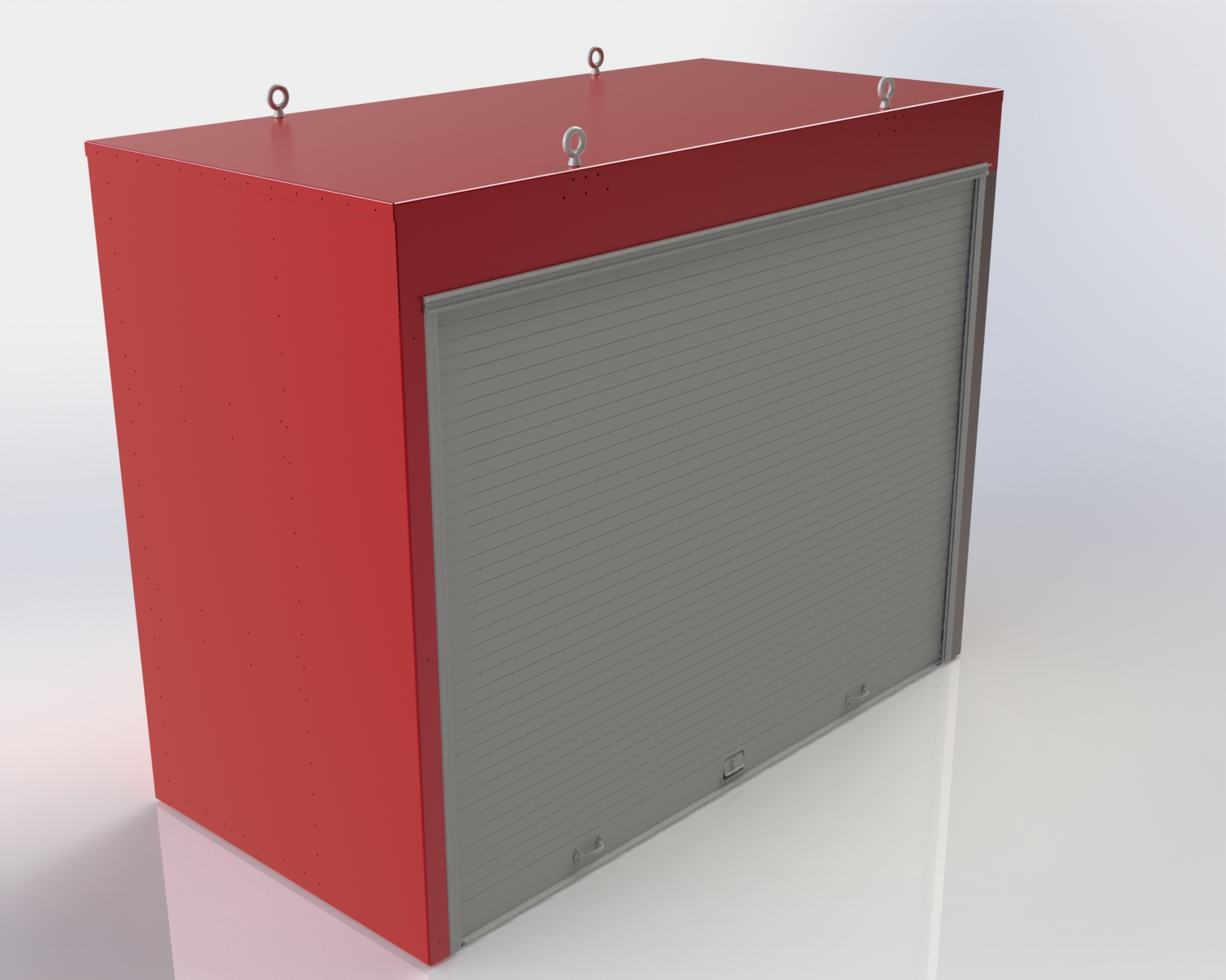
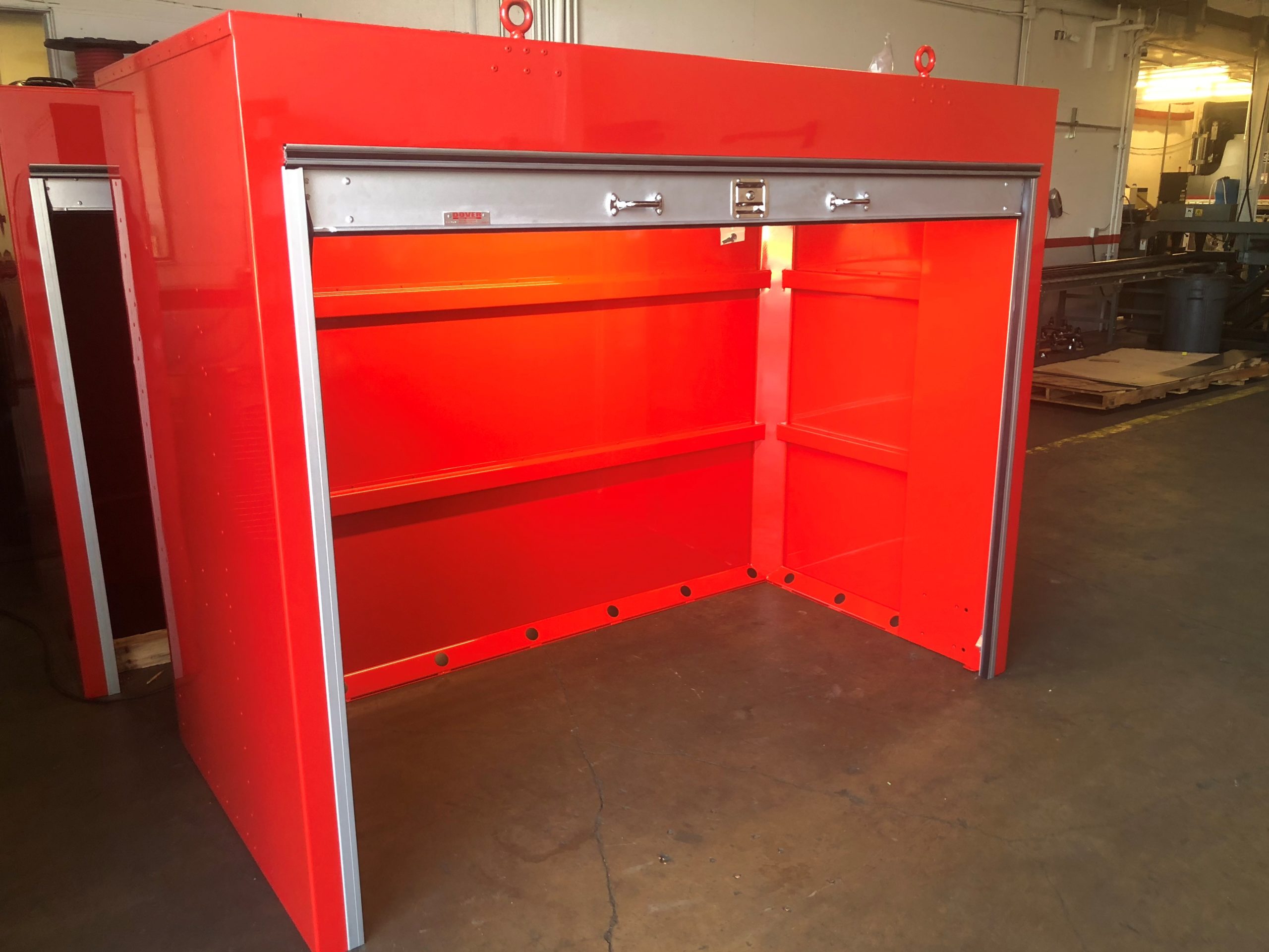
When an aerospace company needed a tool storage solution for their rocket engine test area we were tasked with coming up with a way to secure large wheeled tool carts and protect them from the environment in a harsh desert climate.
Solution:
In order to withstand the abuse of life on a rocket test stand in the middle of the desert, we knew that we needed to design using components that could withstand heat, cold, impact, lots of UV sunlight, and of course the normal wear and tear of an industrial facility. It was for these reasons that we selected to use 10 gauge (.135”) mild steel for the body, and supports, and coat the box in a 2-coat epoxy paint designed for harsh environments.
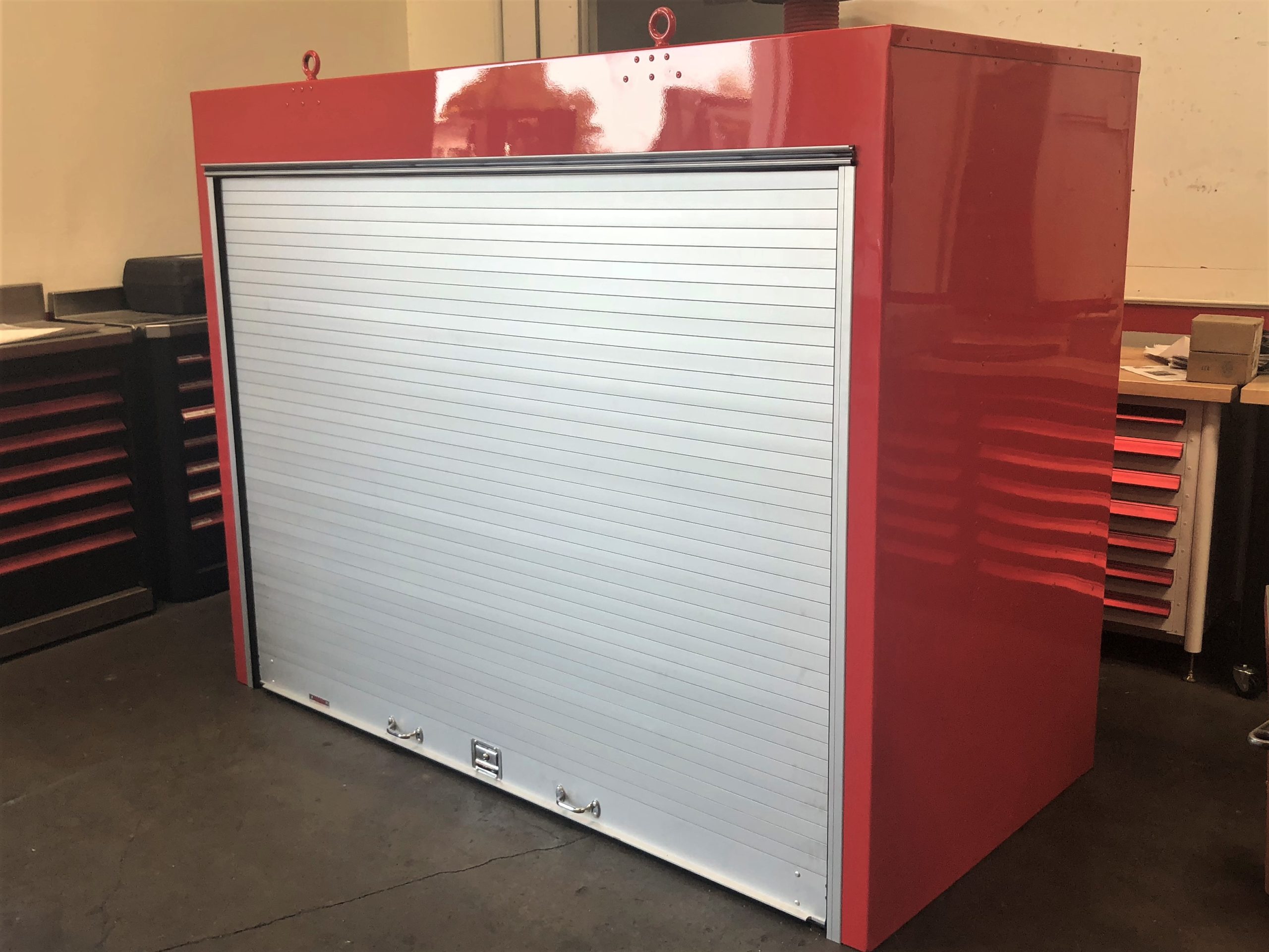
To be able to have security, as well as quick access and durability we chose to use Diamond Rollup Doors. The Diamond doors are built for harsh environments and seal out the wind and the rain.
Since the work on a rocket test stand can run at night we incorporated LED fluorescent lights to give users a bright view. Electrical outlets were also added to allow for charging stations for phones, computers, and batteries.
Our solution ended up being the perfect solution to roll large toolboxes into a safe and secure storage when they were not being used.
The Results:
This custom toolbox was an elegant solution to a storage problem that not only looked amazing, but built to last, and improved the operation in several ways including:
- Decrease in wasted time traveling to get tools
- Convenient area to charge and store batteries
- Better protection of their tools resulting in less maintenance.
- Reduced safety exposure
13610 Immanuel Rd, Pflugerville, TX 78660
ADDRESS
