Blog

Manipulate-1280x960.jpg

The Challenge:

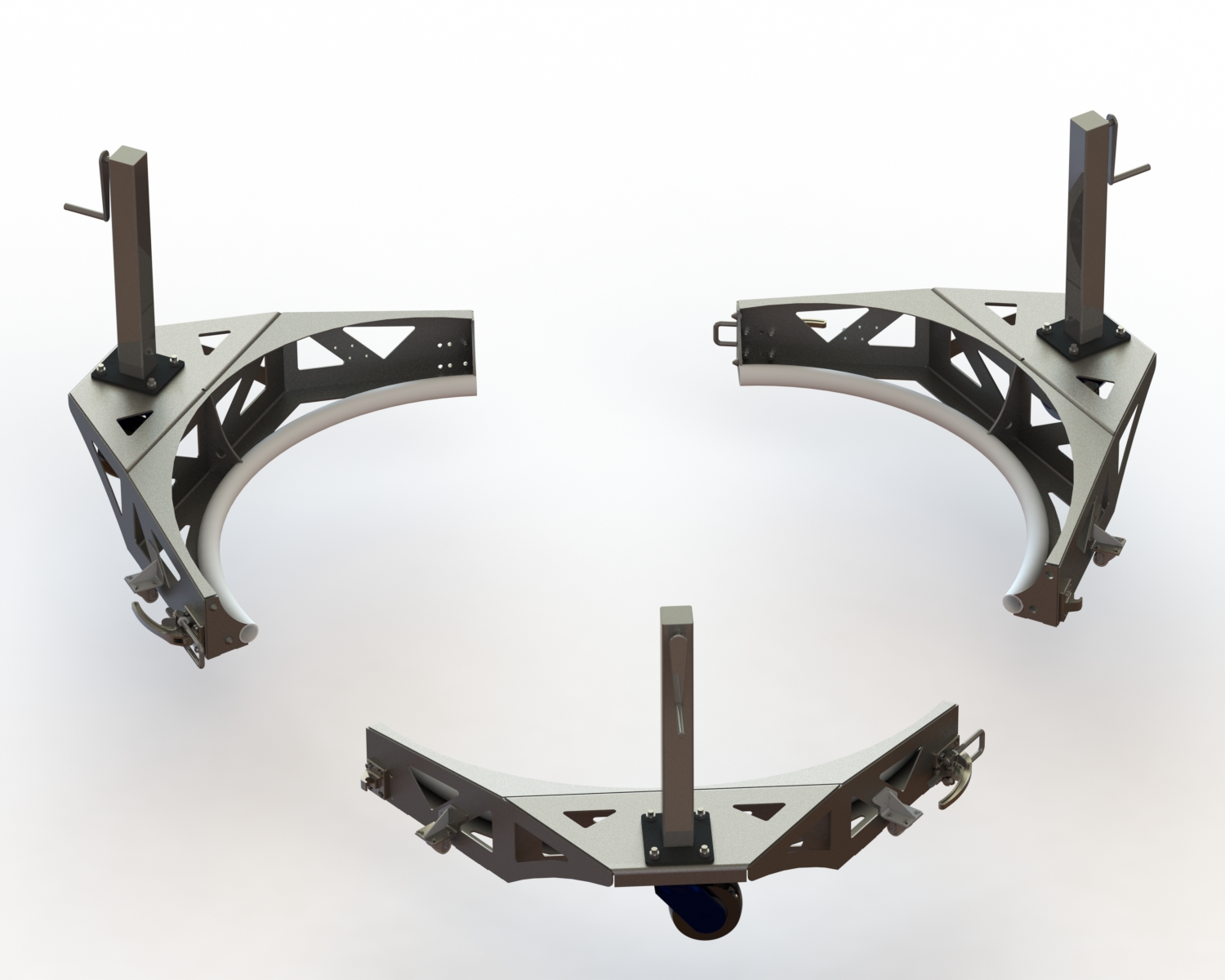
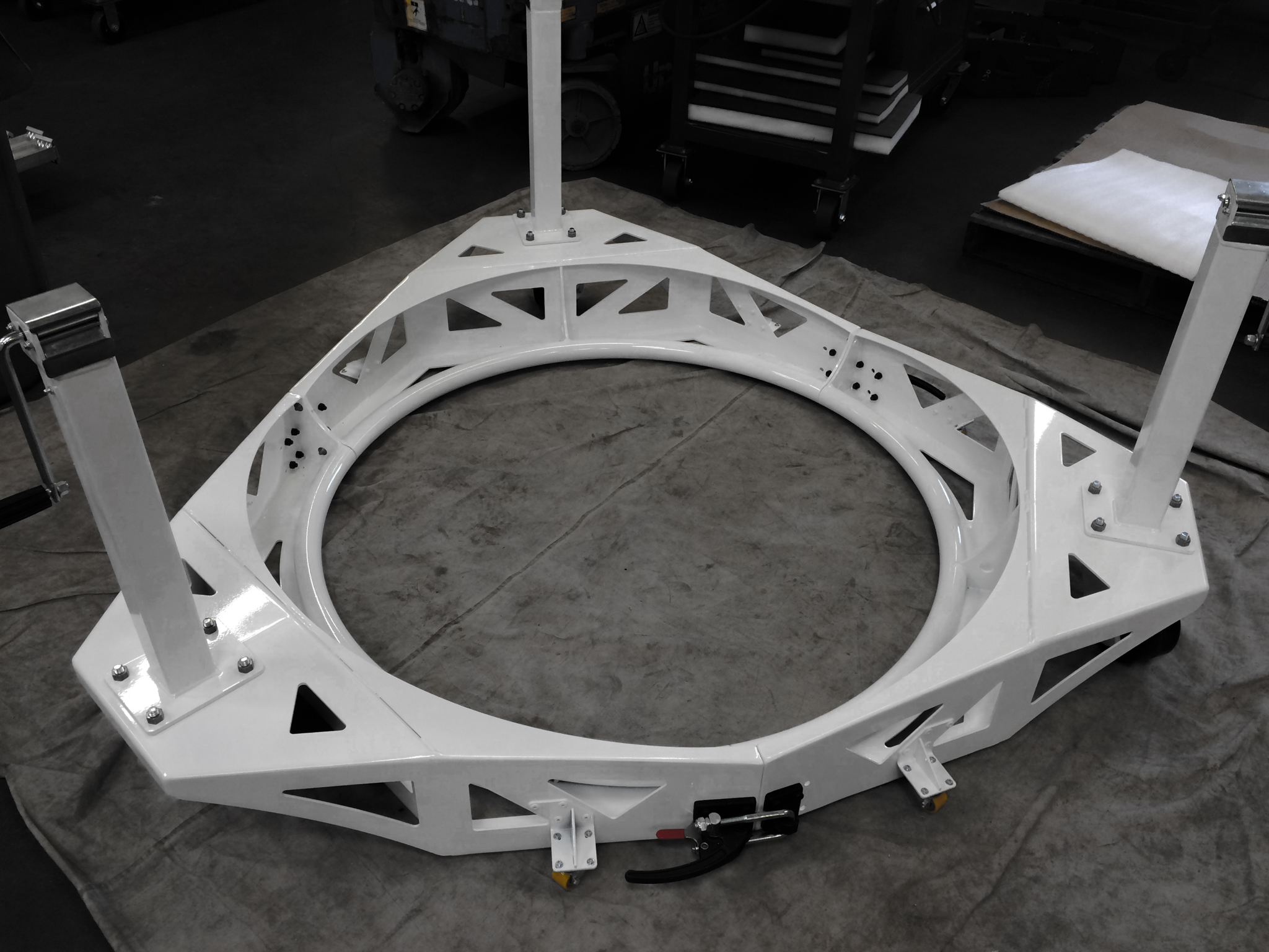
We needed to make a custom industrial material handling system in record time.  A large international corporation had a bunch of oddly shaped, highly delicate, and heavy devices they needed moved into a building in Europe in 2 weeks.  This required that we design a custom industrial material handling solution for them with no room for error in record time.

The Solution:

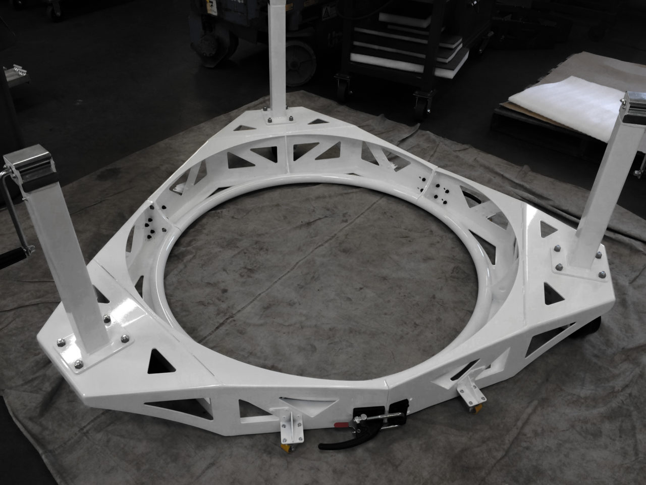
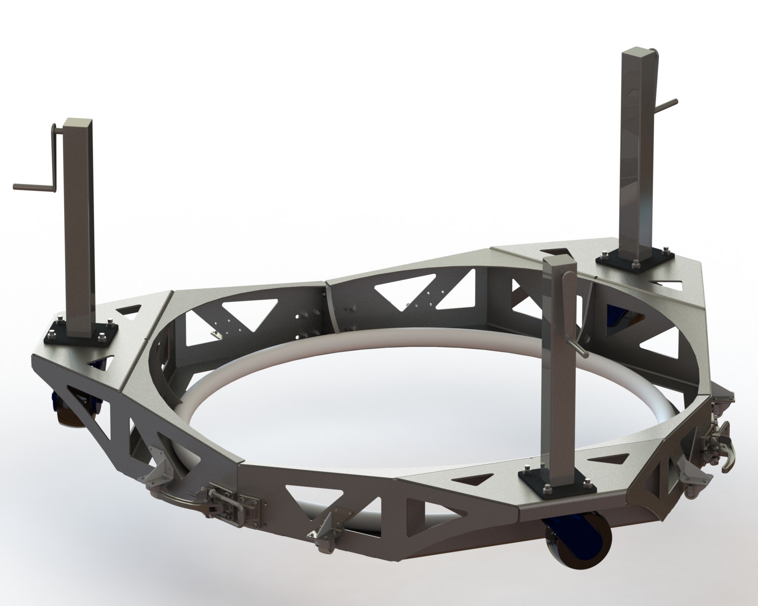
With years of experience designing systems to lift, and manipulate large piece of bridge structures, Daniel Hester was the right engineer to design a solution that would work seamlessly.  It took just a few long days to design and engineer a system utilizing Solidworks that could be built in the shop and tested in less than a week from the initial phone call.  The final design was of a 3-piece assembly that could be disassembled to be air-freighted, as well as be able to move through a standard doorway.  The system allows a single user to move a 2,400 LB object with ease without the need for specialized training of additional equipment.  In addition to it’s strength, it also had to be designed to be cushioned at the points where it touched so that it didn’t damage the structure of the part, or it’s surface finish.  To accomplish this, a high precision ring was made with a rubber pad attached to hold it firm, but cushioned.  Because these units ship via air-freight the unit breaks down into a crate that is easy to move with a pallet jack or forklift and requires only one wrench to assemble after it is delivered.
Custom Device Mover

The Results:

The product worked perfectly for the customer who subsequently ordered many more units that were shipped all over the world.  Because of the fixturing system that we designed for this project we were able to copy-exact manufacture this product with only a few days lead time on future orders.

  • The success of the project resulted in dozens of units shipped around the globe
  • Significantly reduced labor costs for the customer
  • Eliminated the need for heavy machinery
  • Eliminated the need for high skilled craft personnel
  • Reduced safety exposure
Material Handling Equipment

HUET-Dunker-1280x1024.jpg

HUET Trainer

The Challenge:

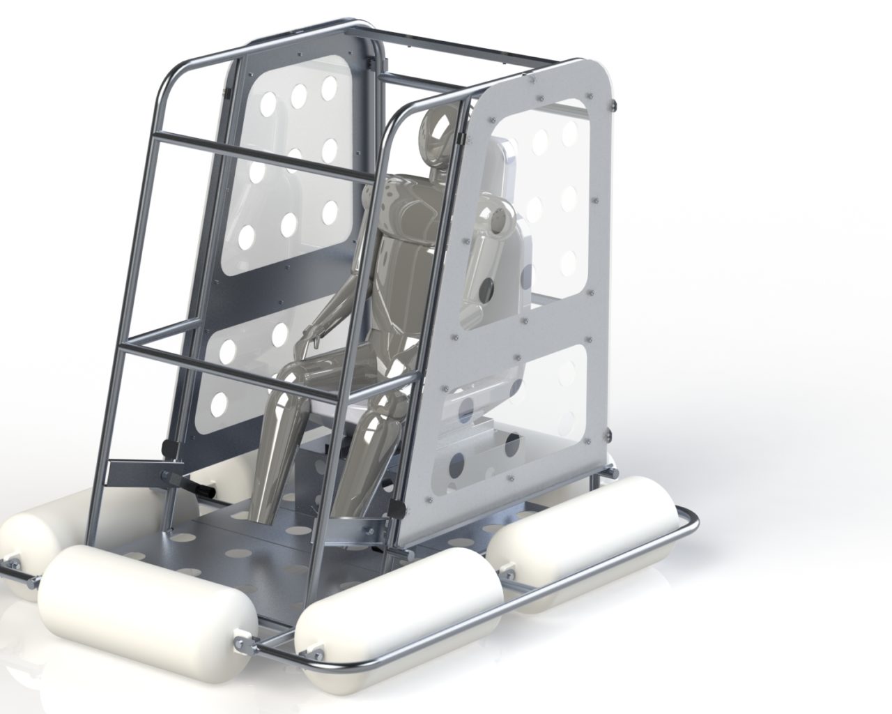
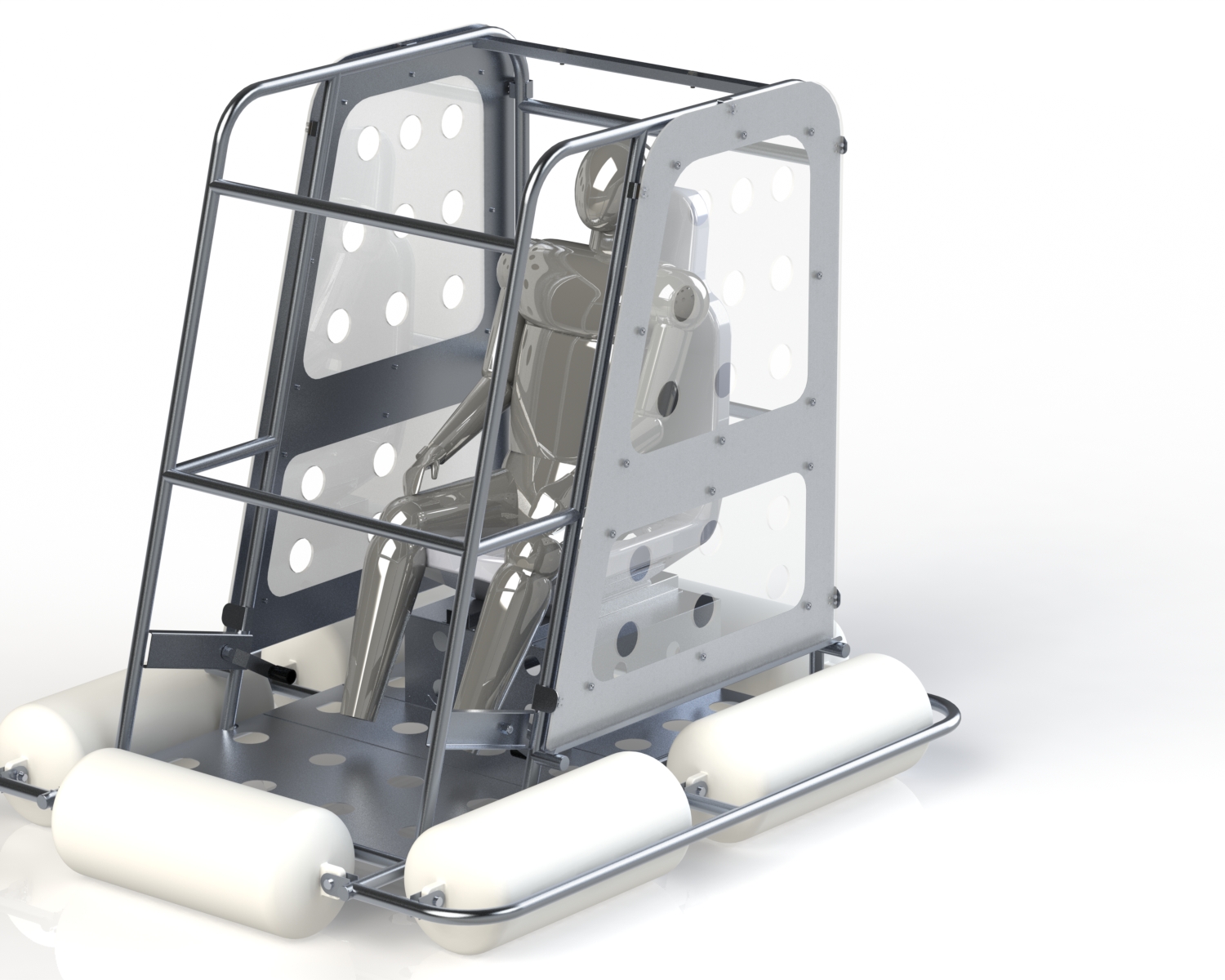
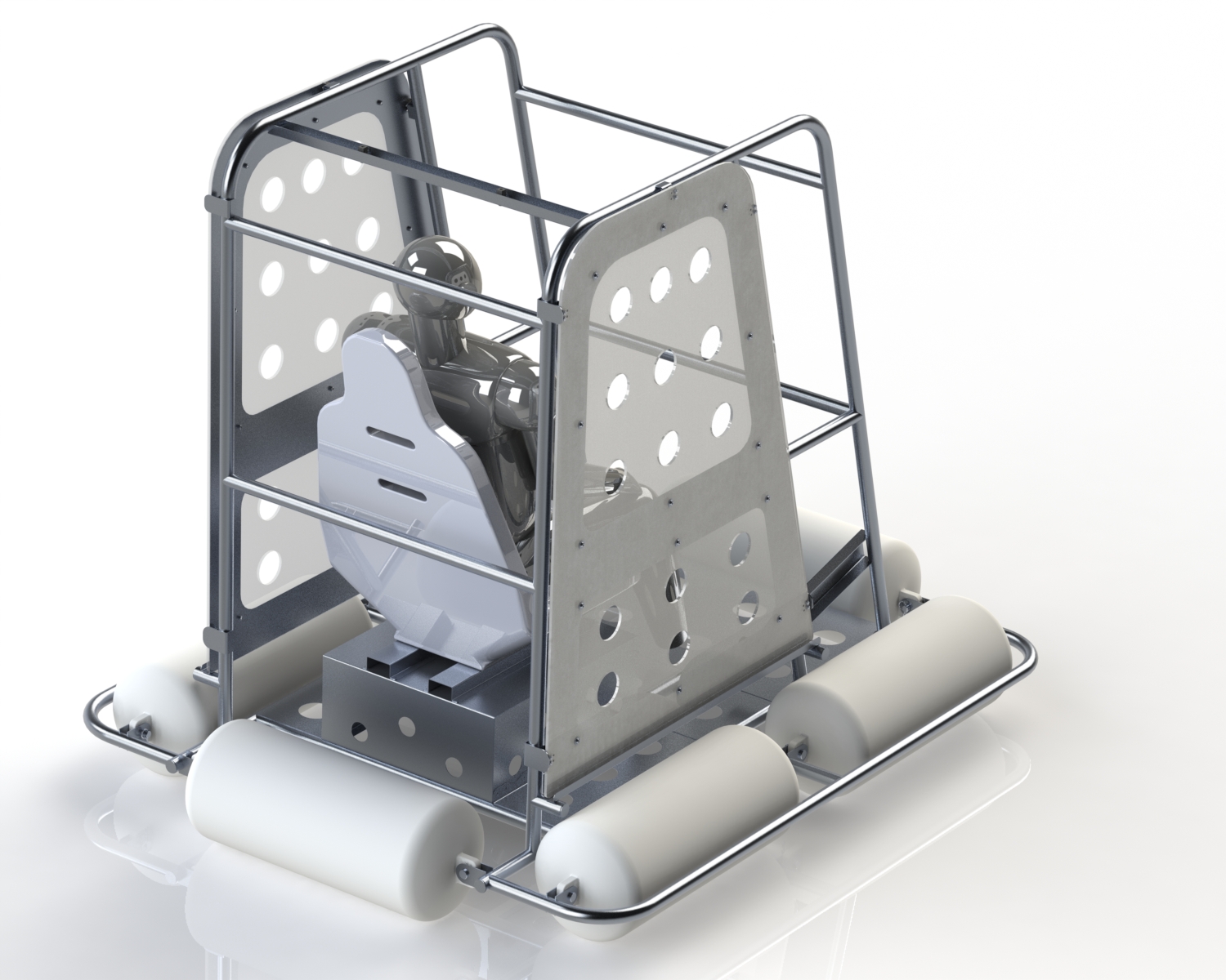
The challenge of this project was to design and build a simulated helicopter cockpit to be light enough to handle by two people, and able to be dunked upside down in a pool.

A police helicopter unit needed a platform that matched the interior dimensions of their helicopters that could be flipped over in a pool to simulate escaping a helicopter during a water landing.

The Solution:

We started the design of this structure by taking careful measurements of the cockpit of the police helicopter.  Taking this data, we designed the structure in Solidworks which not only allowed us to design parts for manufacturing, but let us provide 3D images to the police unit so that they could verify that our design met their design concept.

Because this structure needed to be manually handled, weight was a significant constraint.  It also had to have features such as headphone jacks, and door release levers to simulate the sequence the pilot would do in an actual emergency.

In order to keep the structure light, we utilized a chassis made of 1” aluminum tubing and .0625” 5052 aluminum sheetmetal.  The aluminum and plexiglass doors were attached the chassis with magnets so that the pilot would have to push on the door hard to get it to unlatch, like what would occur in an actual emergency.

HUET

The Results:

The HUET device that we designed and built resulted in several improvements for the police helicopter unit that include:

  • Lightweight training device that can be transported easily in a pickup truck
  • Ergonomically similar to an actual helicopter
  • Increased safety of police helicopter pilots


Smasher-7-1280x1024.jpg

Custom Machine Design

Hydraulic H-Frame Press Design


The Challenge:

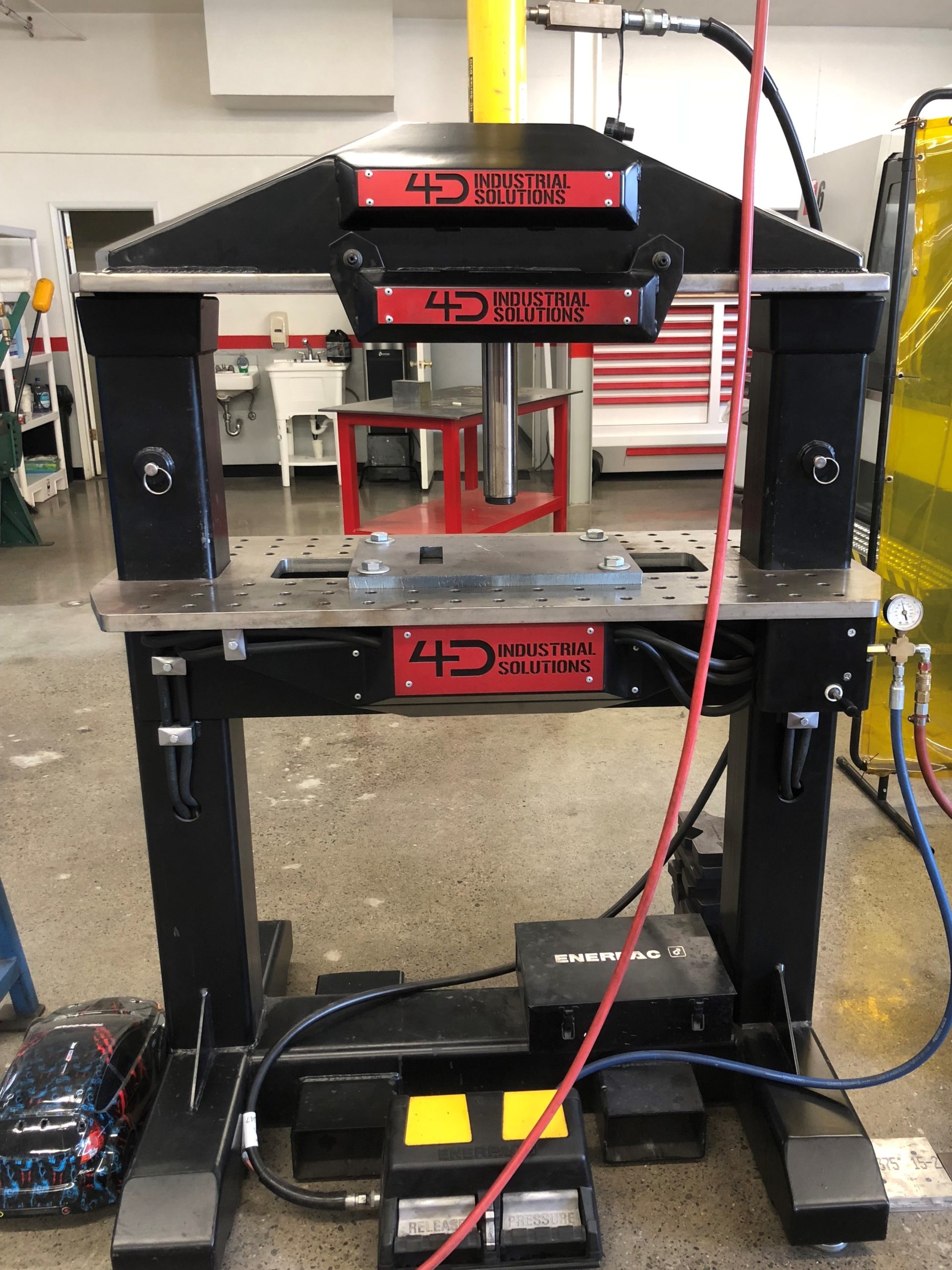
The challenge was to design a simple, safe, and efficient H-frame press that was to be used hard every day of its long life.  Almost every shop in the world has an H-Frame press.  And almost ever single one of them is cumbersome, unsafe, and inefficient so we wanted to design a custom H-Frame hydraulic press that would improve safety, productivity, and ease of use.


Hydraulic Press Design

The Solution:

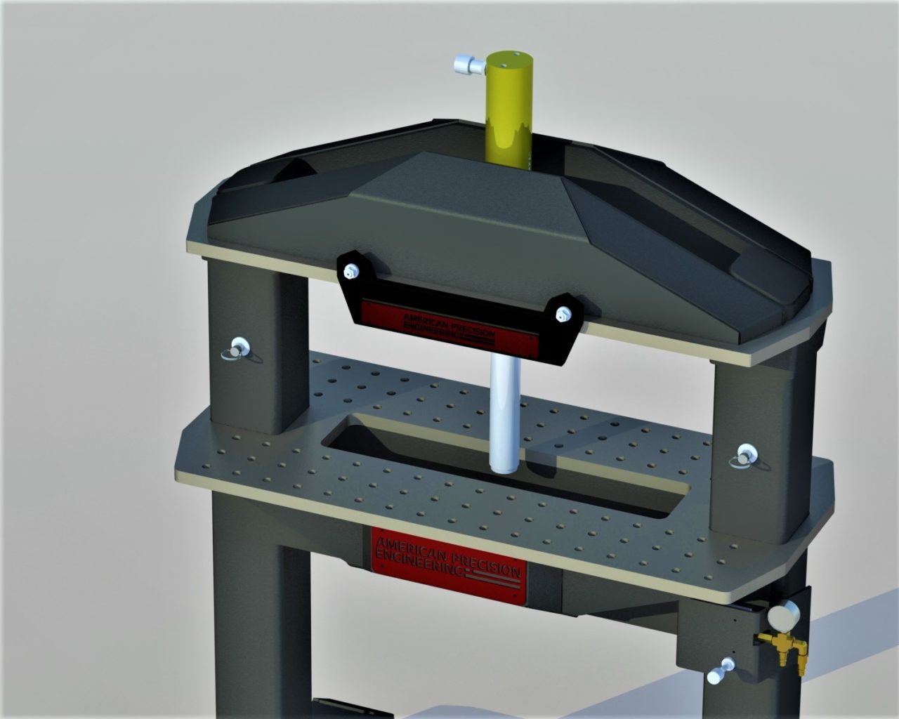
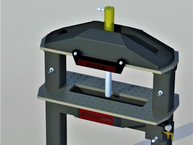
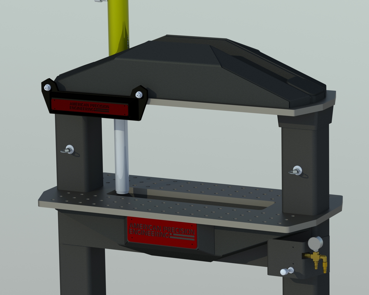
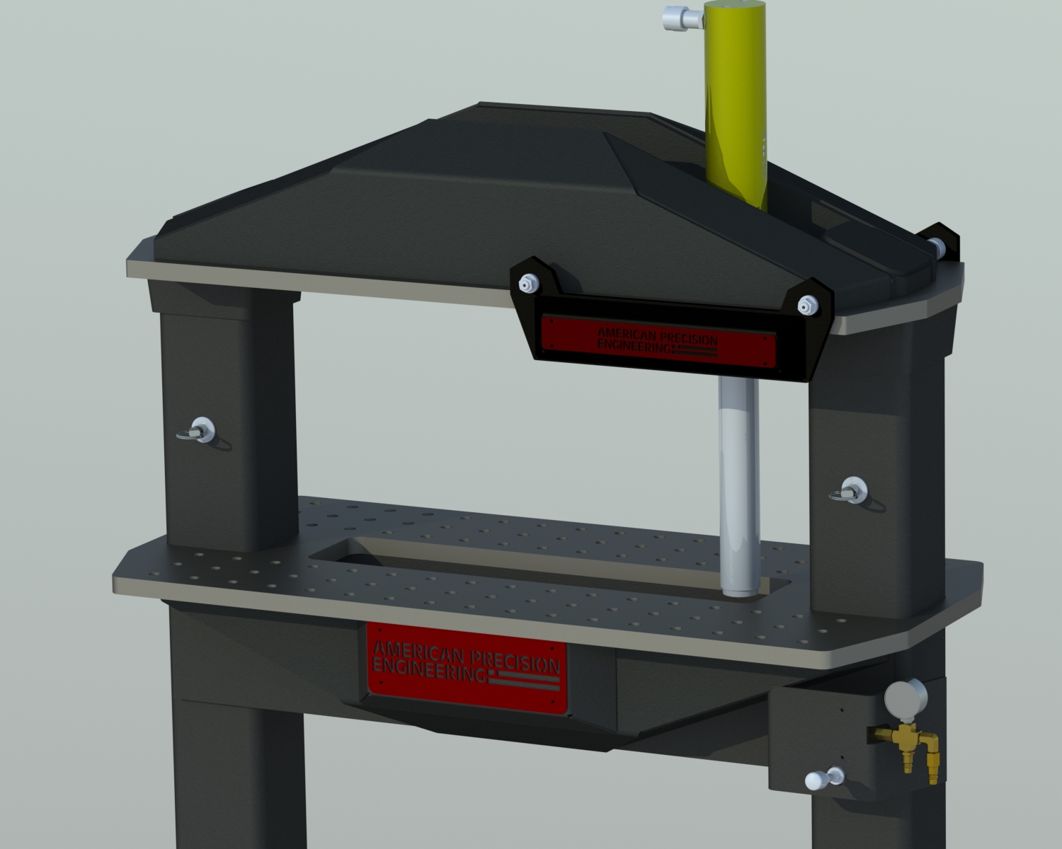
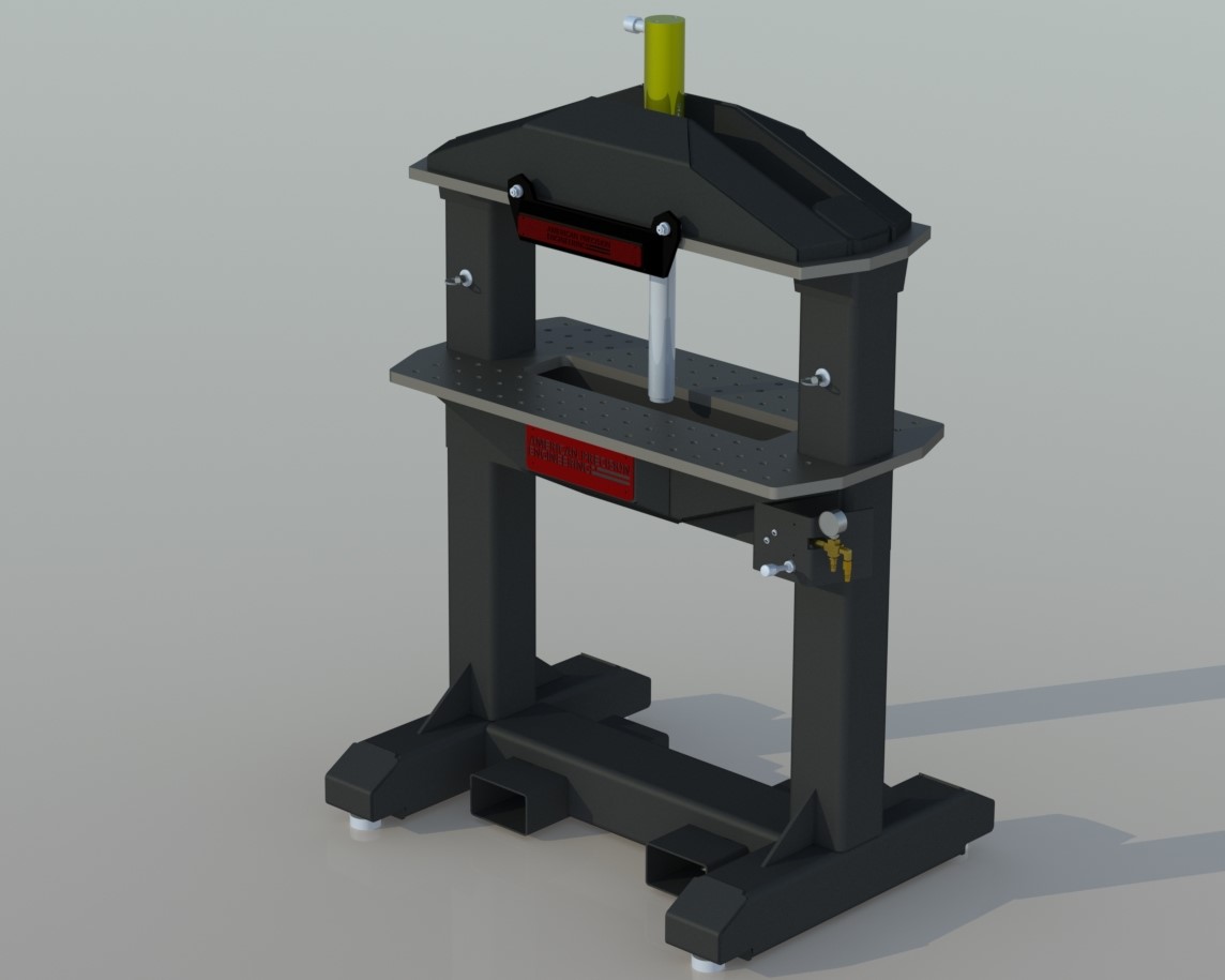
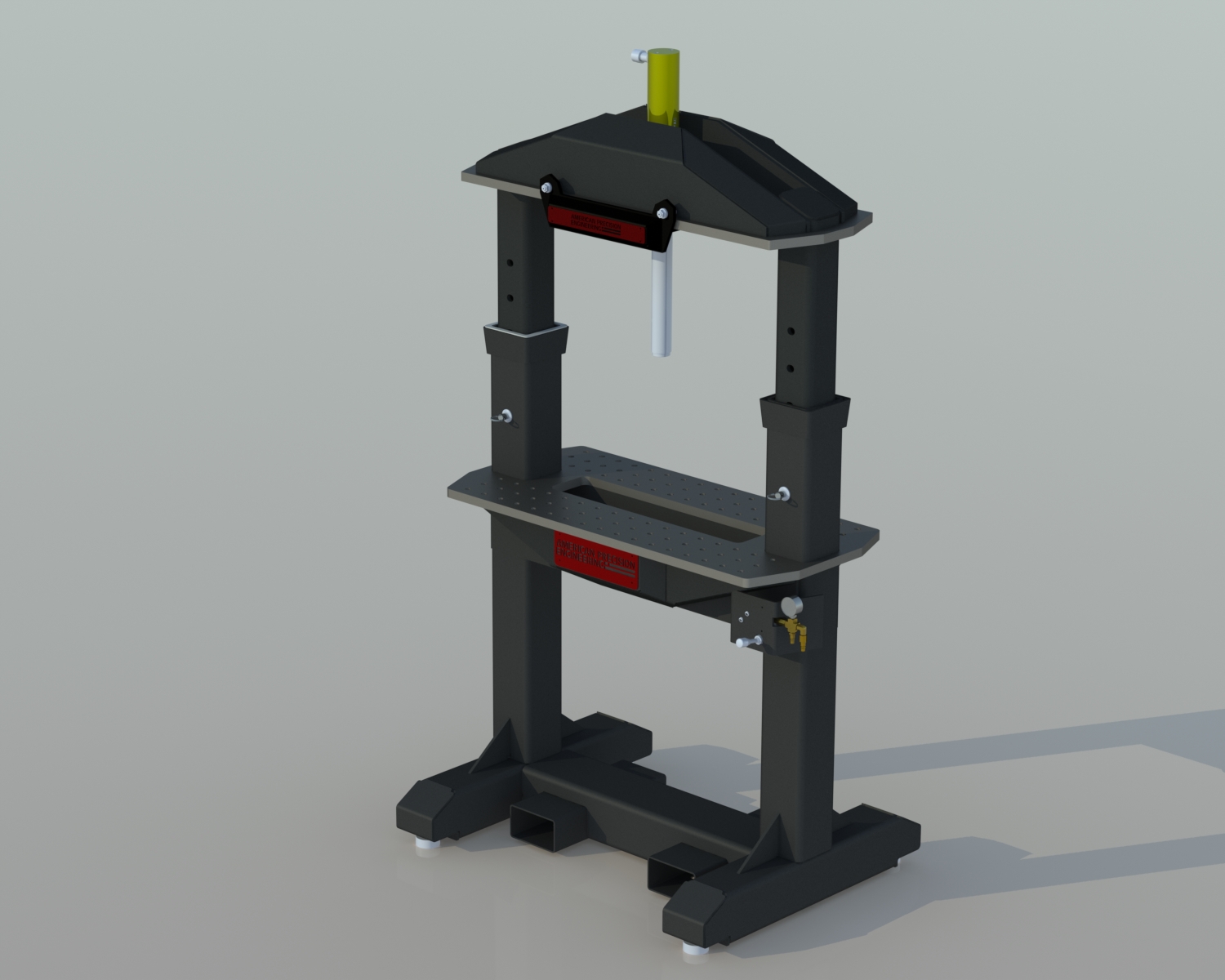
The fabrication of the custom H-Frame hydraulic press started by designing the machine using Solidworks CAD software.  Because we are always striving to optimize the ergonomics of any manufacturing operation, we decided to design the press the opposite way of every other press.  Instead of the work surface having to be adjusted to fit the piece in the press as standard units are designed, we designed our press to have the work surface stationary and have the hydraulic cylinder support be adjustable not just horizontally, but vertically. This allows a wide range of part sizes and shapes to be worked on at an optimized working position, which improves safety, and productivity.

While most presses require either multiple people, a forklift, or some combination of these to adjust, we designed our press to be adjustable by a single operator in seconds.  To make adjusting simple and easy, we utilized pneumatic cylinders to adjust the massive upper press section through a single hand lever.   The horizontal adjustment is accomplished through sliding the hydraulic section on precision cam bearings to its needed location.

The 30 ton hydraulic cylinder is powered by an Enerpac air/hydraulic pump that is foot operated.  Since the pump is air powered as well, it means that nothing more than shop air is needed to power this entire system.  Having a foot-controlled hydraulic cylinder frees up the operators hands to support large pieces when needed which eliminates the need for a helper.

Because flexibility is important in lean manufacturing, we designed the press to also be able to be moved quickly, and safely with nothing more than a pallet jack.  This allows the press to easily be moved to the best location in the shop depending on the current work-flow of the projects.


Hydraulic Press Design
Hydraulic Press

The cylinder can be moved from left to right easily by hand 


Hydraulic Press Design

Upper Assembly in the Lowered Position For Small Components

Hydraulic Press Design

Upper Assembly in the Raised Position For Large Components


The Results:

This custom hydraulic H-Frame press design resulted in a wide range of improvements for the shop including:

  • An efficient, production grade hydraulic press used daily with minimal maintenance.
  • Improved operator safety over standard H-frame presses.
  • Improved worker ergonomics because of its standard working height.
  • Improved productivity in tasks such as broaching, pressing bearings, straightening, and dimpling.
  • One of the coolest looking tools in any shop.

Custom Hydraulic Press


edit5-1280x853.jpg

Custom Machine Design

Portable Jib Crane


Portable Jib Crane

The Challenge:

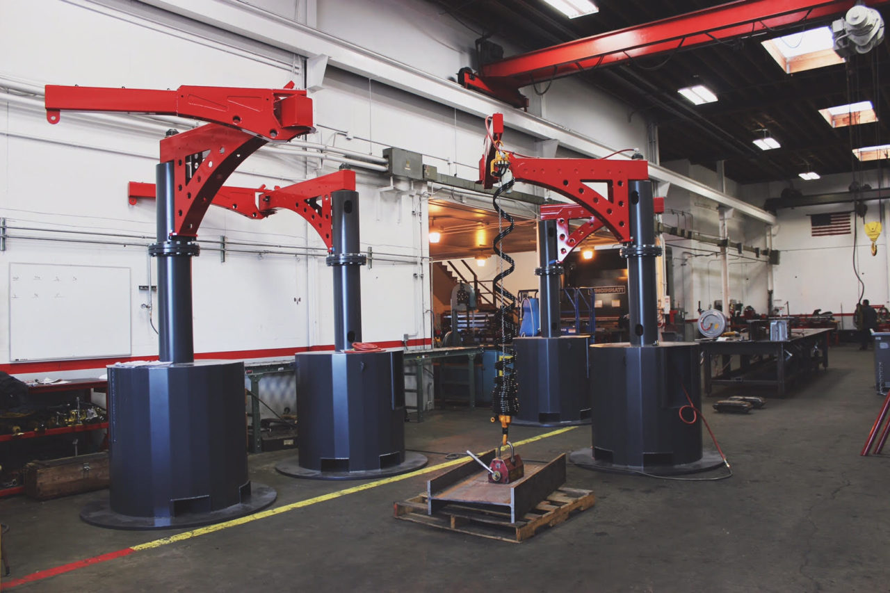
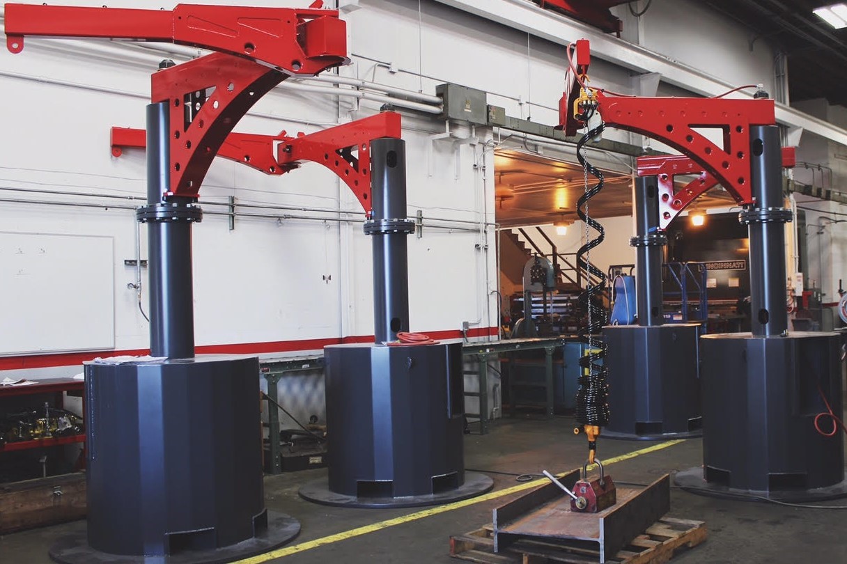
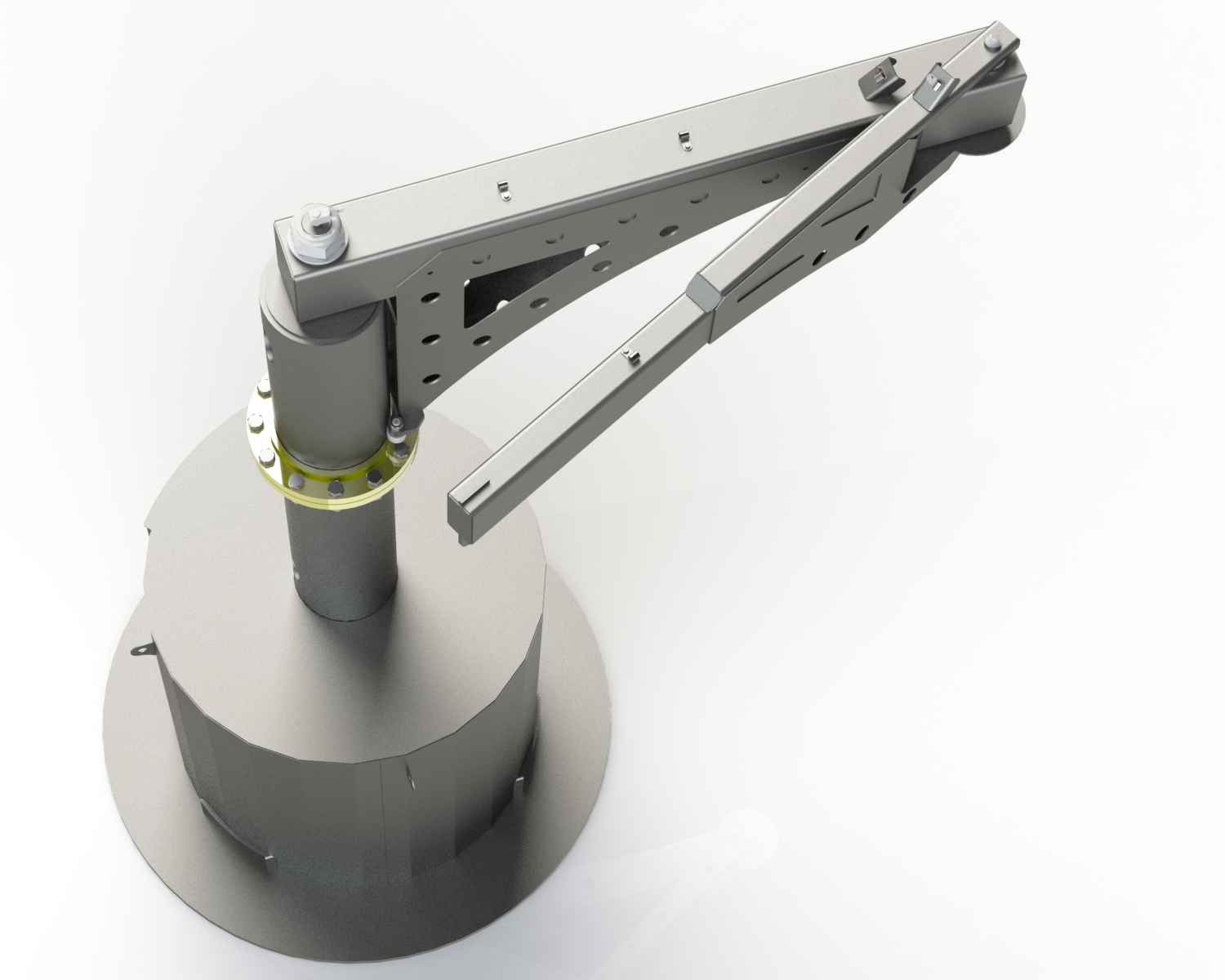
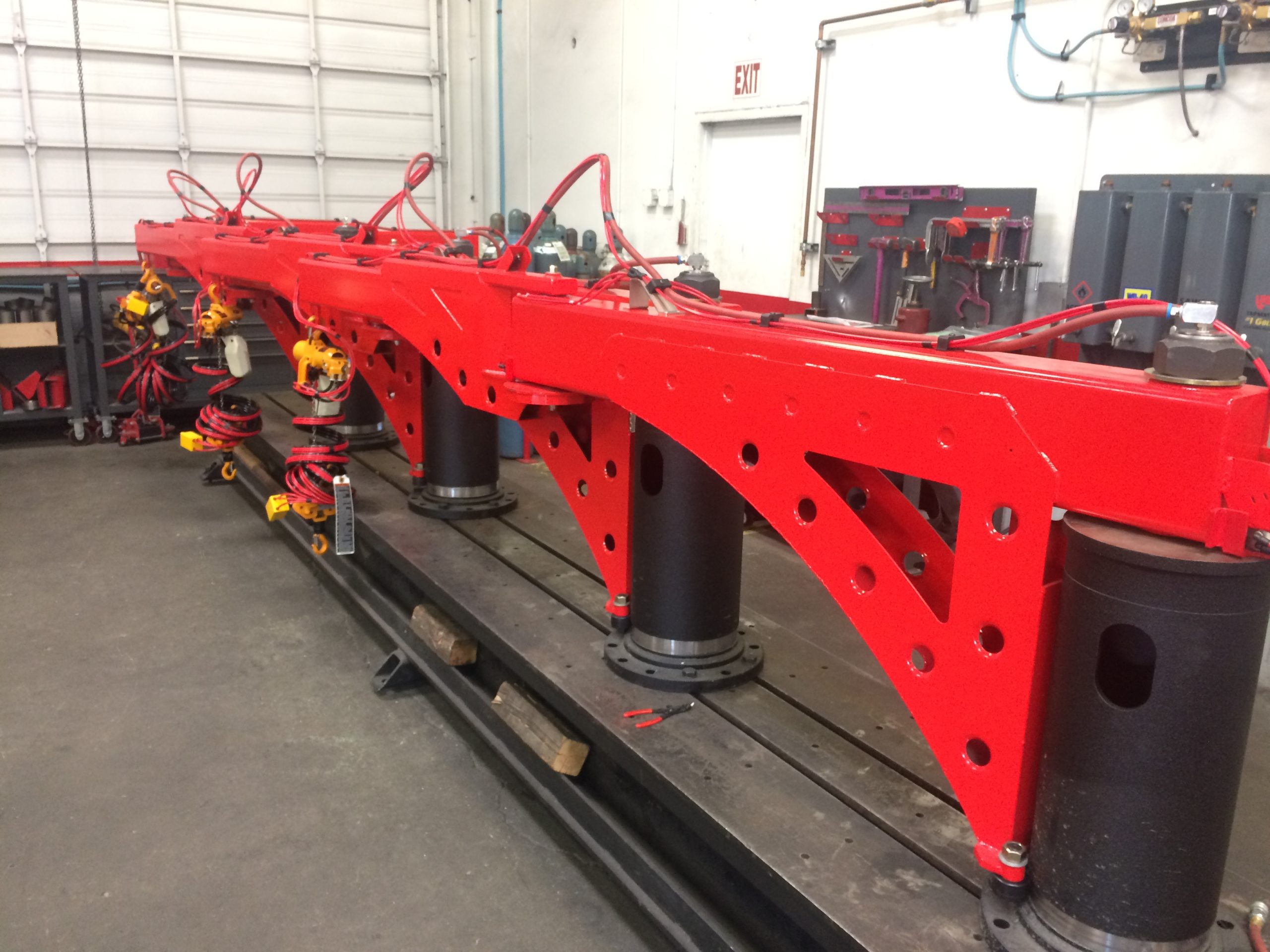
We were challenged to design and build a portable jib crane to be used in an industry manufacturing facility.  A manufacturing company had to lift a component that weighed 150 LBs constantly throughout the course of their manufacturing process.  This amount of weight is just a little too heavy to handle by hand, but too small to make sense moving constantly with a bridge crane.  This required that a custom hoisting solution be created to safely, efficiently, and productively hoist the component through the different manufacturing steps.  In addition, the work bays were constantly changing to adjust to the projects, so the crane needed to be portable to keep the flexibility of the manufacturing floor layout.


Jib Crane

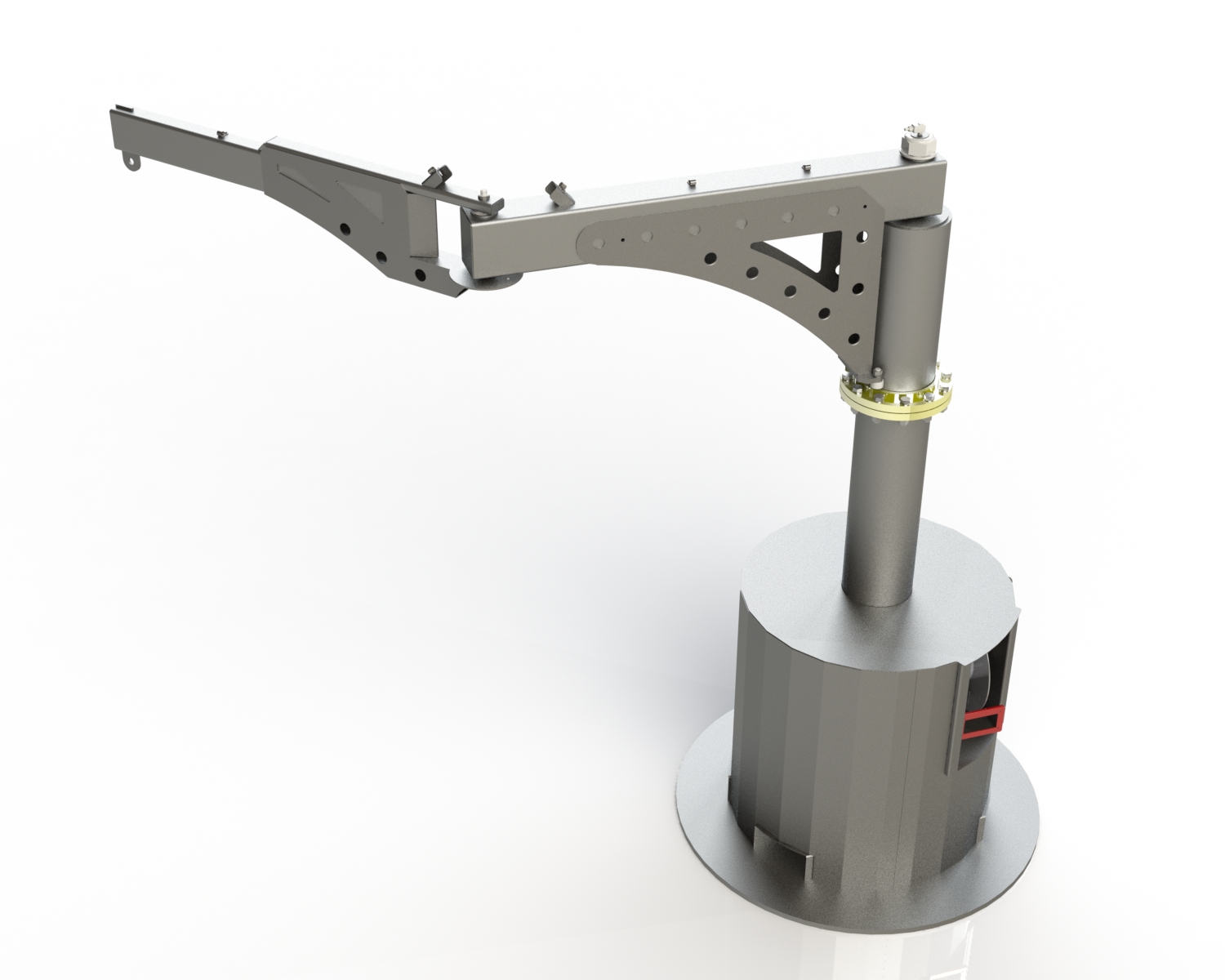
Solidworks allows every piece of hardware to be put into the model to gain efficiency throughout fabrication and assembly


Design:

To design the portable jib crane, we had to consider many variables that included power supply, geometric constraints, code compliance, ergonomics, and ease of use.  After careful analysis of the different stakeholder concerns, we were ready to start designing the crane utilizing Solidworks for both component design as well as finite element analysis.  Once simulated the various load cases, and calculated the capacity per OSHA, ASME, and CMAA standards we sent our design out for 3rd party verification and Professional Engineer’s stamp.

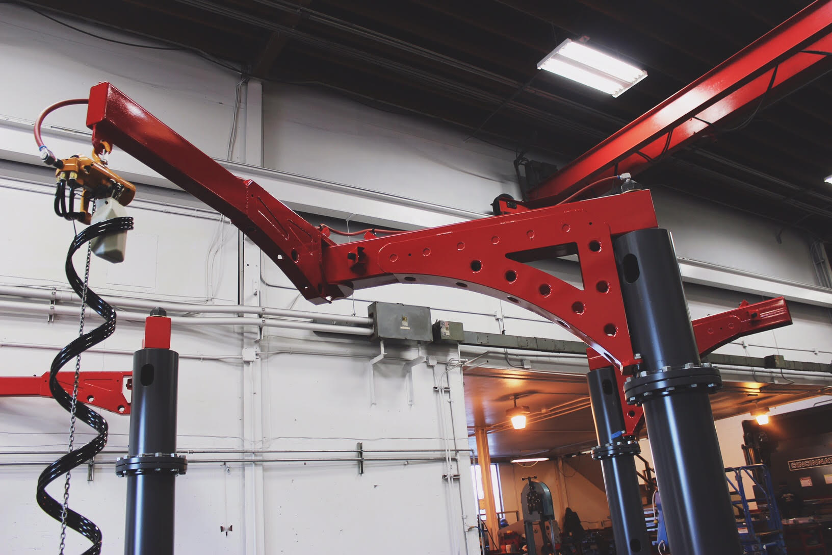
Our design allows for 360 degree rotation of the main boom, and 320 degrees of rotation of the secondary boom which allows for a compact, fast, and easy to use crane.  Because the hoist, as well as the swing brake are air-operated the only power that is required to run the crane is compressed shop air, and the built-in hose reel makes it fast and easy to position it anywhere in the shop and be running immediately, even outside, or in wet conditions.

An additional unique feature that we built into the portable jib crane design was that it has a splice in the main support post.  This splice allows it to be disassembled for shipment inside of a standard shipping container.  In addition it also makes the manufacturing process easier by allowing the main boom assembly to be built on a bench as opposed to 10’ in the air.


Portable Jib Crane

Portable Jib Crane Designed for Lean Manufacturing


Portable Jib Crane

The Double Articulating Crane Boom Allows for Working in Tight Areas


Fabrication:

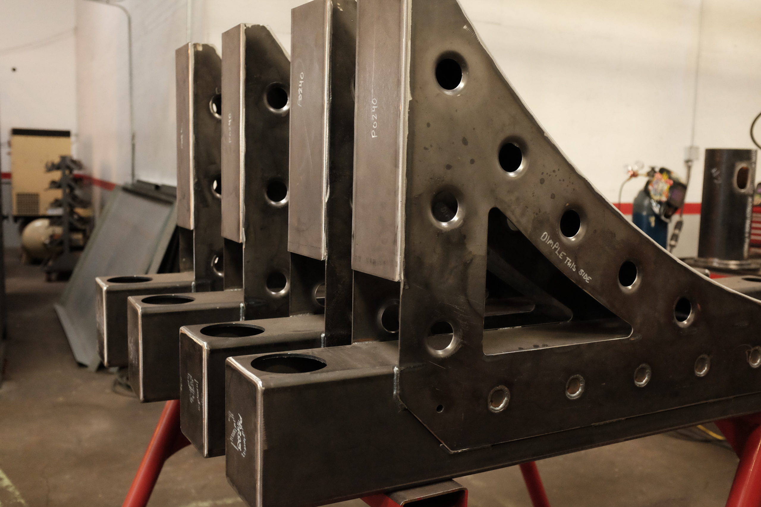
The fabrication of the portable jib crane required a wide range of operations ranging from small part machining, large diameter lathe turning, press brake forming, and lots of critical welding.  The sequence of work, as well as the manufacturing tolerances had to carefully be analyzed so that we could assure proper functionality after assembly.

Because we always think about how something will be built as we design it, many features were built into the design to aid in the fabrication process to aid in tighter tolerance, and easier part assembly.  This includes tab & slot sheetmetal features, Cleco alignment holes, and indexing features to aid in forming sheetmetal components.

After the fabrication was complete a series of load tests were completed across the full range of the crane to proof test both structural and tipping capacity.


The Results:

In the end, the portable jib crane resulted in a range of improvements in the manufacturing shop that included:

  • Increased productivity
  • Reduced safety hazards
  • Can be used in small rooms or when obstacles don’t allow standard jib.
  • Safe and productive operation with minimal training
  • Portable with the use of forklift or pallet jack
  • Can be outdoors or in wet environments


Portable Jib Crane
Portable Jib Crane


ADDRESS


13610 Immanuel Rd, Pflugerville, TX 78660


FOLLOW US AT